RESISTANCE RESISTANCE (HI Beam)
! CAUTION 1. Set the meter selector to the OHMS position.
Always disconnect the battery when performing 2. Connect one tester lead to the brown/black wire;
resistance tests to avoid damaging the multimeter. then connect the other tester lead to the lavender
wire.
NOTE: Perform this test on the switch harness
using the following procedure.
3. With the dimmer switch in the HI position, the
meter must show less than 1 ohm.
NOTE: If the meter shows more than 1 ohm of
resistance, replace the switch.
RESISTANCE (LO Beam)
1. Connect one tester lead to the brown/black wire;
then connect the other tester lead to the white wire.
2. With the dimmer switch in the LO position, the
meter must show an open circuit.
NOTE: If the meter reads resistance, replace the
switch.
KC276A
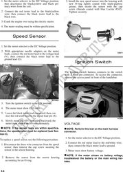
1. Turn the ignition switch to the ON position. RESISTANCE (Emergency Stop)
2. Set the meter selector to the OHMS position. 1. Set the meter selector to the OHMS position.
3. Connect either tester lead to pin B; then connect 2. Connect the one lead to the brown/lavender wire;
the other tester lead to pin A. then connect the other tester lead to the
black/white wire.
4. The meter must show less than 1 ohm.
3. With the switch in the OFF position, the meter 5
5. Turn the ignition switch to the LIGHTS position. must show an open circuit.
The meter must show less than 1 ohm.
4. With the switch in the RUN position, the meter
6. Leaving the tester lead on pin B, connect the other must show less than 1 ohm.
tester lead to pin C.
NOTE: If the meter shows more than 1 ohm of
7. The meter must show less than 1 ohm. resistance, replace the switch.
NOTE: If the meter shows more than 1 ohm of RESISTANCE (Reverse Override)
resistance, replace the switch.
1. Set the meter selector to the OHMS position.
2. Connect one tester lead to one lavender/red wire;
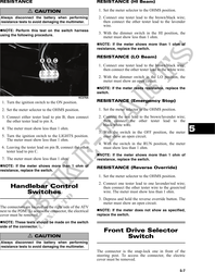
Handlebar Control then connect the other tester wire to the green/red
Switches wire. The meter must show less than 1 ohm.
3. Depress and hold the reverse override button. The
meter must show an open circuit.
The connectors are located on the right side of the ATV
next to the PDM. To access the connector, the electrical NOTE: If the meter does not show as specified,
cover must be removed. replace the switch.
NOTE: These tests should be made on the switch
side of the connector.
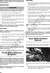
Front Drive Selector
! CAUTION Switch
Always disconnect the battery when performing
resistance tests to avoid damaging the multimeter.
The connector is the snap-lock one in front of the
steering post. To access the connector, the electric
cover must be removed.
5-7