Shift Lever
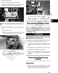
CHECKING ADJUSTMENT
KC194A
3. Tighten the jam nuts securely; then shift the trans-
mission to each position and verify correct adjust-
ment.
4. Install the left-side engine cover and seat making
sure the seat locks securely in place. 2
KC165
With the engine stopped and the brake lever lock
engaged, turn the ignition switch to the ON position; Frame/Welds/Racks
then shift the transmission into each of the gear posi-
tions and note that the gear position indicated on the
LCD corresponds to the gear position selected by the
lever. The frame, welds, and racks should be checked period-
ically for damage, bends, cracks, deterioration, broken
If the indicator does not correspond to the selected components, and missing components. If replacement
gear, it will be necessary to test drive the ATV to deter- or repair constitutes removal, see Section 8.
mine if the gear shift position switch is faulty or the
shift lever needs adjustment.
If the ATV functions in the gear selected by the shift Electrical Connections
lever, troubleshoot the gear shift position switch (see
Section 5).
The electrical connections should be checked periodi-
If the ATV functions but the shift lever does not corre- cally for proper function. In case of an electrical fail-
spond with the gear indicated on the LCD, adjust the ure, check fuses, connections (for tightness, corrosion,
shift linkage. To adjust, proceed to ADJUSTING. damage), and/or bulbs. If an electrical component
ADJUSTING needs to be tested for proper function, see Section 5.
1. Remove the seat; then remove the left-side engine
cover. Hydraulic Brake
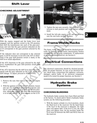
2. With the ignition switch in the ON position, loosen Systems
jam nut (A) (left-hand threads); then loosen jam
nut (C) and with the shift lever in the reverse posi-
tion, adjust the coupler (B) until the transmission CHECKING/BLEEDING
is in reverse and the "R" icon appears on the LCD.
The hydraulic brake systems have been filled and bled
at the factory. To check and/or bleed a hydraulic brake
system, use the following procedure.
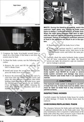
1. With the master cylinder in a level position, check
the fluid level in the reservoir. On the hand brake
if the level in the reservoir is adequate, the sight
glass will appear dark. If the level is low, the sight
glass will appear clear. On the auxiliary brake the
level must be between the MIN and MAX lines on
the reservoir.
2-15