NOTE: When testing the HI fuse holder, the head- 2. Connect the black tester lead to ground.
light dimmer switch must be in the HI position;
when testing the LIGHTS fuse holder, the headlight 3. The meter reading must be within specification.
dimmer switch can be in either position. NOTE: If the meter does not show as specified,
replace ignition coil.
NOTE: If the meter shows no battery voltage,
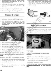
troubleshoot the battery, switches, distribution Spark Plug Cap
module, or the main wiring harness.
1. Connect the red tester lead to one end of the cap;
then connect the black tester lead to the other end
of the cap.
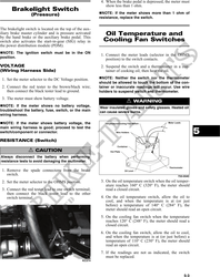
Fuses
! CAUTION
Always disconnect the battery when performing
resistance tests to avoid damaging the multimeter.
1. Set the meter selector to the OHMS position.
2. Connect the red tester lead to one spade end of the
fuse; then connect the black tester lead to the other
spade end.
3. The meter must show less than 1 ohm resistance. AR603D
If the meter reads open, replace the fuse. 2. The meter reading must be within specification.
NOTE: Make sure the fuses are returned to their
NOTE: If the meter does not read as specified,
proper position according to amperage. Refer to
replace the spark plug cap.
the fuse block cover for fuse placement.
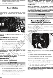
PEAK VOLTAGE 5
Ignition Coil NOTE: All of the peak voltage tests should be
made using the Fluke Model 73 Multimeter with
Peak Voltage Reading Adapter. If any other type of
tester is used, readings may vary due to internal
The ignition coil is on the frame above the engine. To circuitry.
access the coil, the left side panel must be removed.
NOTE: The battery must be at full charge for
RESISTANCE these tests.
! CAUTION Primary/CDI
Always disconnect the battery when performing
resistance tests to avoid damaging the multimeter.
NOTE: The CDI is located on the electrical tray in
front of the steering shaft.
NOTE: For these tests, the meter selector should
be set to the OHMS position and the primary
wire(s) should be disconnected.
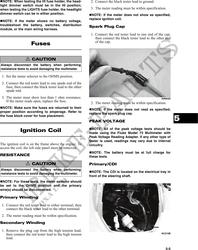
Primary Winding
1. Connect the red tester lead to either terminal; then
connect the black tester lead to the other terminal.
2. The meter reading must be within specification.
Secondary Winding
1. Remove the plug cap from the high tension lead;
then connect the red tester lead to the high tension KC210B
lead.
5-5