mxu 400 Manuel atelier : Page 66

Microfiches
Image preview

Page 64

Image preview

Page 65

Image preview

Page 67

Image preview

Page 68

1 5 10 15 20 25 30 35 40 45 50 55 60 65 70 75 80 85 90 95 100 105 110 115 120 125 130 135 137
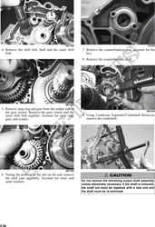
          14. Slide the fixed drive face assembly onto the front
    shaft.
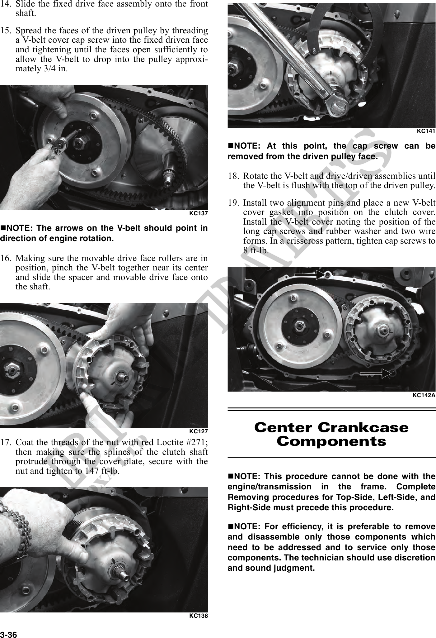
15. Spread the faces of the driven pulley by threading
    a V-belt cover cap screw into the fixed driven face
    and tightening until the faces open sufficiently to
    allow the V-belt to drop into the pulley approxi-
    mately 3/4 in.


                                                                                                              KC141

                                                            NOTE: At this point, the cap screw can be
                                                          removed from the driven pulley face.

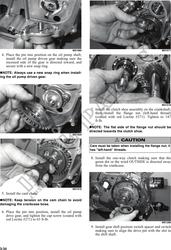
                                                          18. Rotate the V-belt and drive/driven assemblies until
                                                              the V-belt is flush with the top of the driven pulley.
                                                          19. Install two alignment pins and place a new V-belt
                                                  KC137       cover gasket into position on the clutch cover.
                                                              Install the V-belt cover noting the position of the
 NOTE: The arrows on the V-belt should point in               long cap screws and rubber washer and two wire
direction of engine rotation.                                 forms. In a crisscross pattern, tighten cap screws to
                                                              8 ft-lb.
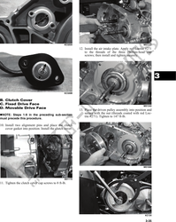
16. Making sure the movable drive face rollers are in
    position, pinch the V-belt together near its center
    and slide the spacer and movable drive face onto
    the shaft.


                                                                                                             KC142A


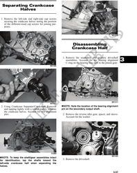
                                                  KC127          Center Crankcase
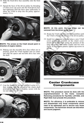
17. Coat the threads of the nut with red Loctite #271;             Components
    then making sure the splines of the clutch shaft
    protrude through the cover plate, secure with the
    nut and tighten to 147 ft-lb.
                                                           NOTE: This procedure cannot be done with the
                                                          engine/transmission in the frame. Complete
                                                          Removing procedures for Top-Side, Left-Side, and
                                                          Right-Side must precede this procedure.

                                                           NOTE: For efficiency, it is preferable to remove
                                                          and disassemble only those components which
                                                          need to be addressed and to service only those
                                                          components. The technician should use discretion
                                                          and sound judgment.


                                                  KC138


3-36