mxu 400 Manuel atelier : Page 71

Microfiches
Image preview

Page 69

Image preview

Page 70

Image preview

Page 72

Image preview

Page 73

1 5 10 15 20 25 30 35 40 45 50 55 60 65 70 75 80 85 90 95 100 105 110 115 120 125 130 135 137
          Measuring Connecting Rod                                    2. Acceptable width range must be within specifica-
(Big End Width)                                                tions.

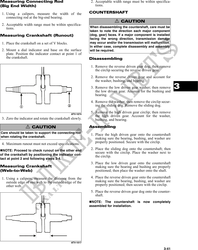
 1. Using a calipers, measure the width of the              COUNTERSHAFT
    connecting rod at the big-end bearing.
                                                                            ! CAUTION
 2. Acceptable width range must be within specifica-
    tions.                                                  When disassembling the countershaft, care must be
                                                            taken to note the direction each major component
Measuring Crankshaft (Runout)                               (dog, gear) faces. If a major component is installed
                                                            facing the wrong direction, transmission damage
 1. Place the crankshaft on a set of V blocks.              may occur and/or the transmission will malfunction.
                                                            In either case, complete disassembly and assembly
 2. Mount a dial indicator and base on the surface          will be required.
    plate. Position the indicator contact at point 1 of
    the crankshaft.                                         Disassembling

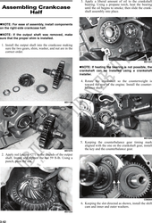
                                                            1. Remove the reverse driven gear dog; then remove
                                                               the circlip securing the reverse driven gear.
                                                            2. Remove the reverse driven gear and account for
                                                               the washer, bushing, and bearing.
                                                            3. Remove the low driven gear washer; then remove
                                                               the low driven gear. Account for the bushing and
                                                                                                                     3
                                                               bearing.
                                                            4. Remove the washer; then remove the circlip secur-
                                                               ing the sliding dog. Remove the sliding dog.

                                                 ATV-1074
                                                            5. Remove the high driven gear circlip; then remove
                                                               the high driven gear. Account for the washer,
 3. Zero the indicator and rotate the crankshaft slowly.       bushing, and bearing.

                 ! CAUTION                                  Assembling
Care should be taken to support the connecting rod
                                                            1. Place the high driven gear onto the countershaft
when rotating the crankshaft.
                                                               making sure the bearing, bushing, and washer are
 4. Maximum runout must not exceed specifications.             properly positioned. Secure with the circlip.

  NOTE: Proceed to check runout on the other end            2. Place the sliding dog onto the countershaft; then
                                                               secure with the circlip. Place the washer next to
of the crankshaft by positioning the indicator con-
                                                               the circlip.
tact at point 2 and following steps 3-4.
                                                            3. Place the low driven gear onto the countershaft
Measuring Crankshaft                                           making sure the bearing and bushing are properly
(Web-to-Web)                                                   positioned; then place the washer onto the shaft.

 1. Using a calipers, measure the distance from the         4. Place the reverse driven gear onto the countershaft
    outside edge of one web to the outside edge of the         making sure the bearing, bushing, and washer are
    other web.                                                 properly positioned; then secure with the circlip.
                                                            5. Place the reverse driven gear dog onto the counter-
                                                               shaft.
                                                             NOTE: The countershaft is now completely
                                                            assembled for installation.


                                                 ATV-1017

                                                                                                             3-41