Right-Side Components
AT THIS POINT
To service center crankcase components only, pro-
ceed to Removing Right-Side Components.
NOTE: For efficiency, it is preferable to remove
and disassemble only those components which
need to be addressed and to service only those
KC142A
components. The technician should use discretion
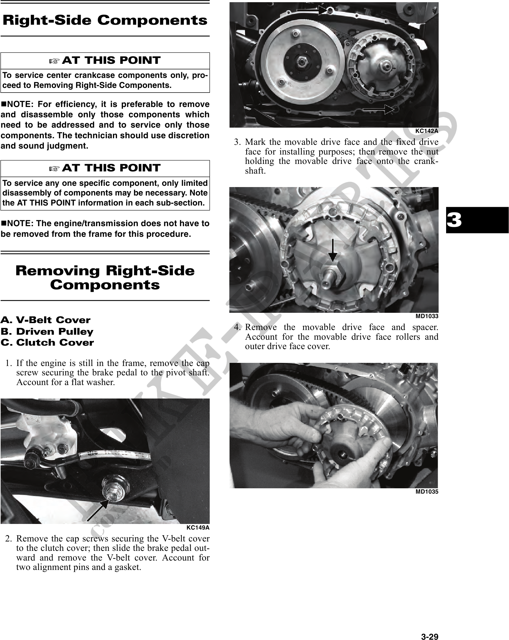
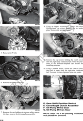
and sound judgment. 3. Mark the movable drive face and the fixed drive
face for installing purposes; then remove the nut
holding the movable drive face onto the crank-
AT THIS POINT shaft.
To service any one specific component, only limited
disassembly of components may be necessary. Note
the AT THIS POINT information in each sub-section.
NOTE: The engine/transmission does not have to
be removed from the frame for this procedure.
3
Removing Right-Side
Components
MD1033
A. V-Belt Cover
B. Driven Pulley 4. Remove the movable drive face and spacer.
Account for the movable drive face rollers and
C. Clutch Cover outer drive face cover.
1. If the engine is still in the frame, remove the cap
screw securing the brake pedal to the pivot shaft.
Account for a flat washer.
MD1035
KC149A
2. Remove the cap screws securing the V-belt cover
to the clutch cover; then slide the brake pedal out-
ward and remove the V-belt cover. Account for
two alignment pins and a gasket.
3-29