A. Piston still at top-dead-center.
B. Camshaft lobes directed down (toward the pis-
ton).
C. Camshaft alignment marks parallel to the valve
cover mating surface.
D. Recessed side of the sprocket directed toward
the cam lobes.
E. Camshaft alignment pin and sprocket alignment
hole (smallest) are aligned.
! CAUTION MD1137
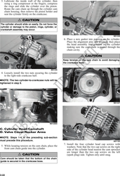
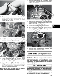
18. Rotate the crankshaft until the second cap screw
If any of the above factors are not as stated, go back
securing the sprocket to the camshaft can be
to step 13 and carefully proceed. installed; then install the cap screw (threads coated
with red Loctite #271). Tighten to 11 ft-lb; then
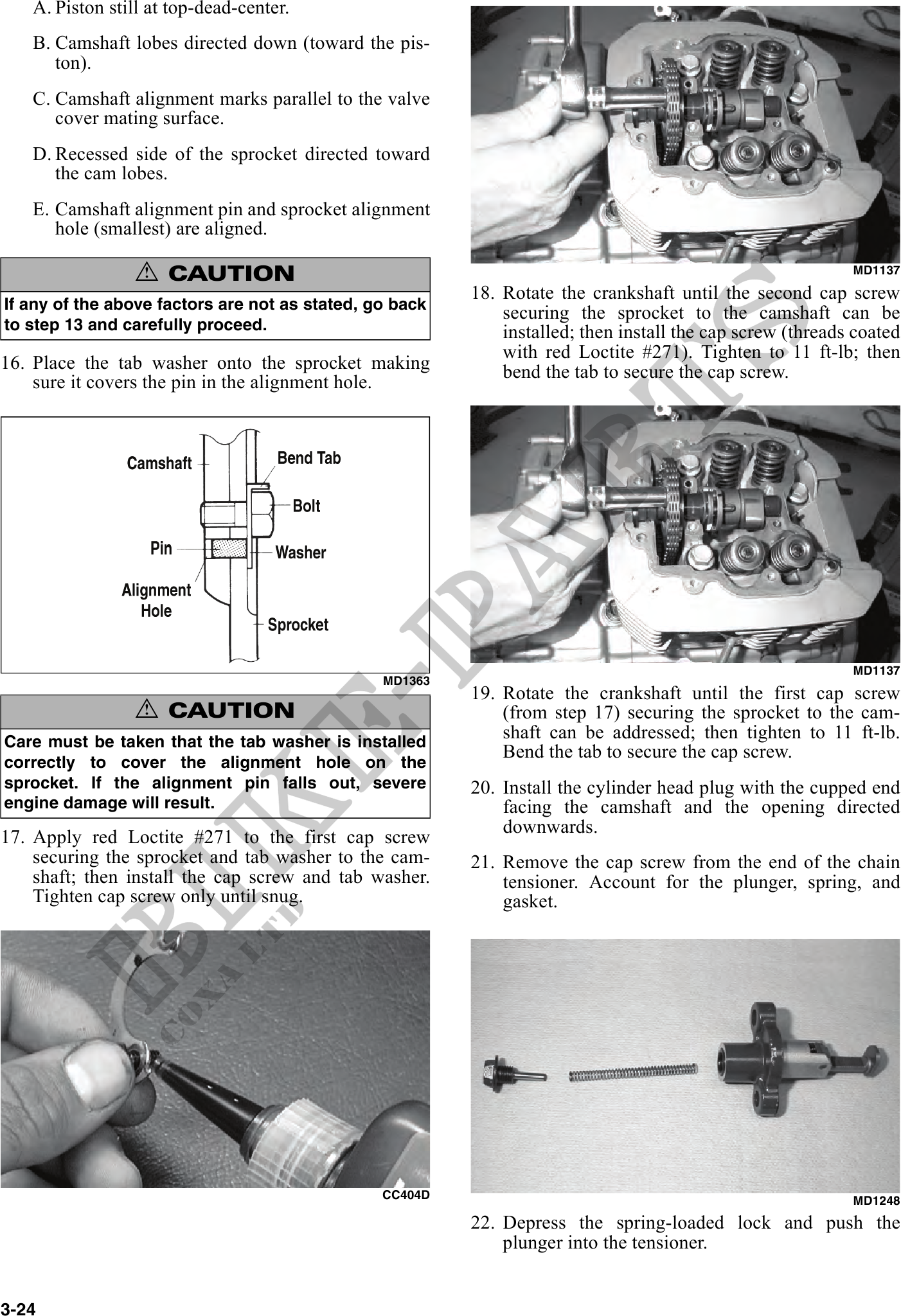
16. Place the tab washer onto the sprocket making bend the tab to secure the cap screw.
sure it covers the pin in the alignment hole.
MD1137
MD1363
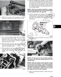
19. Rotate the crankshaft until the first cap screw
! CAUTION (from step 17) securing the sprocket to the cam-
Care must be taken that the tab washer is installed
shaft can be addressed; then tighten to 11 ft-lb.
Bend the tab to secure the cap screw.
correctly to cover the alignment hole on the
sprocket. If the alignment pin falls out, severe 20. Install the cylinder head plug with the cupped end
engine damage will result. facing the camshaft and the opening directed
downwards.
17. Apply red Loctite #271 to the first cap screw
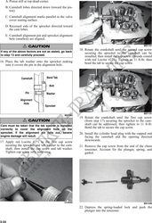
securing the sprocket and tab washer to the cam- 21. Remove the cap screw from the end of the chain
shaft; then install the cap screw and tab washer. tensioner. Account for the plunger, spring, and
Tighten cap screw only until snug. gasket.
CC404D MD1248
22. Depress the spring-loaded lock and push the
plunger into the tensioner.
3-24