Mon Panier

| Désignation | Référence | Qté |
|---|
| Désignation | Référence | Qté |
|---|
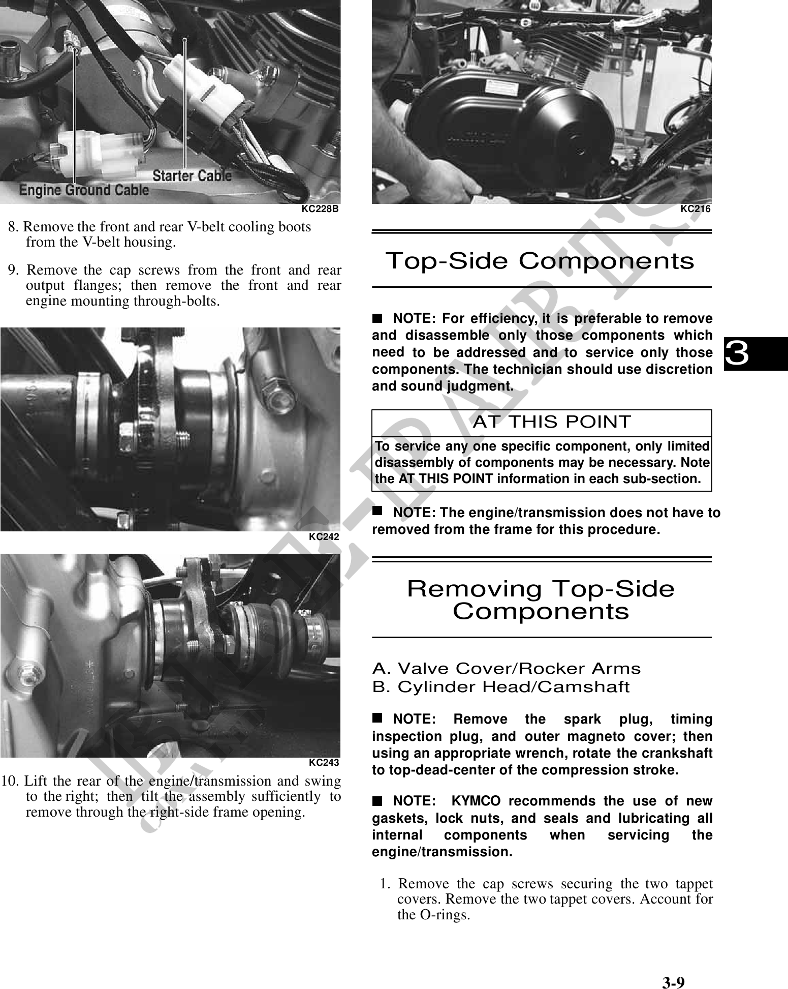
KC228B KC216
8. Remove the front and rear V-belt cooling boots
from the V-belt housing.
9. Remove the cap screws from the front and rear Top-Side Components
output flanges; then remove the front and rear
engine mounting through-bolts.
NOTE: For efficiency, it is preferable to remove
and disassemble only those components which
need to be addressed and to service only those
components. The technician should use discretion
3
and sound judgment.
AT THIS POINT
To service any one specific component, only limited
disassembly of components may be necessary. Note
the AT THIS POINT information in each sub-section.
NOTE: The engine/transmission does not have to
KC242
removed from the frame for this procedure.
Removing Top-Side
Components
A. Valve Cover/Rocker Arms
B. Cylinder Head/Camshaft
NOTE: Remove the spark plug, timing
inspection plug, and outer magneto cover; then
using an appropriate wrench, rotate the crankshaft
KC243
to top-dead-center of the compression stroke.
10. Lift the rear of the engine/transmission and swing
to the right; then tilt the assembly sufficiently to NOTE: KYMCO recommends the use of new
remove through the right-side frame opening. gaskets, lock nuts, and seals and lubricating all
internal components when servicing the
engine/transmission.
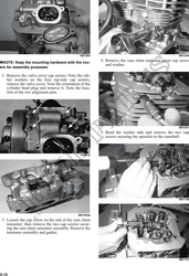
1. Remove the cap screws securing the two tappet
covers. Remove the two tappet covers. Account for
the O-rings.
3-9