mxu 400 Manuel atelier : Page 44

Microfiches
Image preview

Page 42

Image preview

Page 43

Image preview

Page 45

Image preview

Page 46

1 5 10 15 20 25 30 35 40 45 50 55 60 65 70 75 80 85 90 95 100 105 110 115 120 125 130 135 137
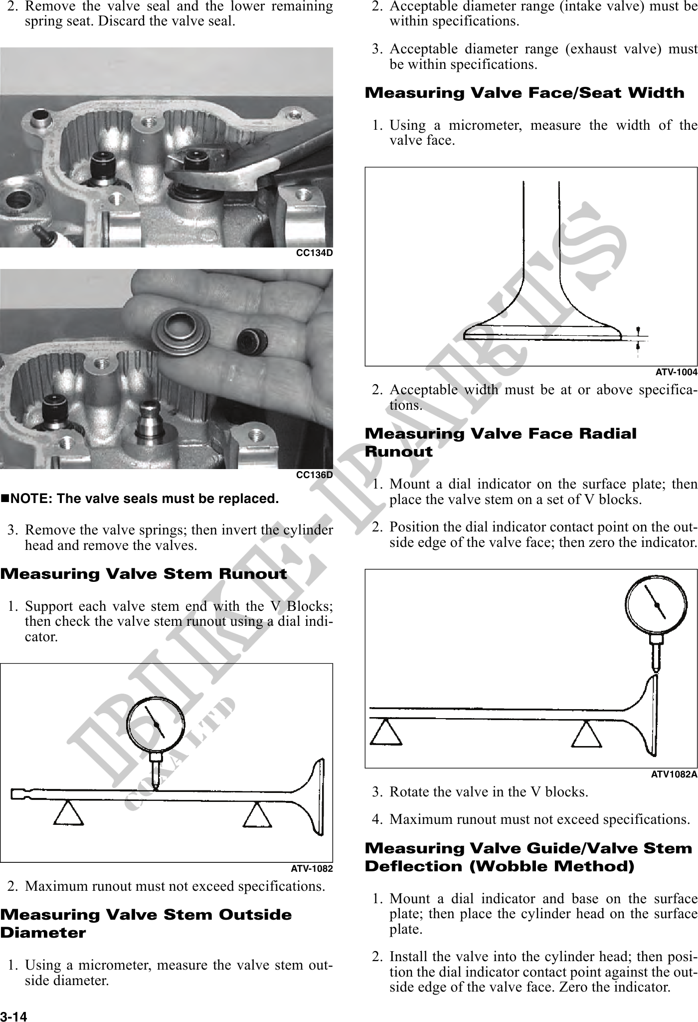
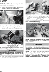
           2. Remove the valve seal and the lower remaining         2. Acceptable diameter range (intake valve) must be
    spring seat. Discard the valve seal.                     within specifications.
                                                          3. Acceptable diameter range (exhaust valve) must
                                                             be within specifications.
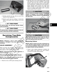
                                                          Measuring Valve Face/Seat Width

                                                          1. Using a micrometer, measure the width of the
                                                             valve face.


                                                CC134D


                                                                                                           ATV-1004
                                                          2. Acceptable width must be at or above specifica-
                                                             tions.
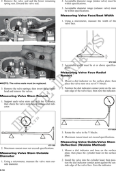
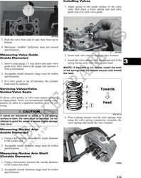
                                                          Measuring Valve Face Radial
                                                          Runout
                                                CC136D
                                                          1. Mount a dial indicator on the surface plate; then
 NOTE: The valve seals must be replaced.                     place the valve stem on a set of V blocks.
 3. Remove the valve springs; then invert the cylinder    2. Position the dial indicator contact point on the out-
    head and remove the valves.                              side edge of the valve face; then zero the indicator.

Measuring Valve Stem Runout

 1. Support each valve stem end with the V Blocks;
    then check the valve stem runout using a dial indi-
    cator.


                                                                                                          ATV1082A
                                                          3. Rotate the valve in the V blocks.
                                                          4. Maximum runout must not exceed specifications.
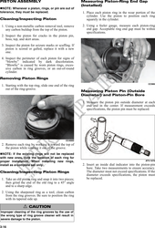
                                                          Measuring Valve Guide/Valve Stem
                                               ATV-1082   Deflection (Wobble Method)
 2. Maximum runout must not exceed specifications.
                                                          1. Mount a dial indicator and base on the surface
Measuring Valve Stem Outside                                 plate; then place the cylinder head on the surface
Diameter                                                     plate.
                                                          2. Install the valve into the cylinder head; then posi-
 1. Using a micrometer, measure the valve stem out-          tion the dial indicator contact point against the out-
    side diameter.                                           side edge of the valve face. Zero the indicator.
3-14