mxu 400 Manuel atelier : Page 41

Microfiches
Image preview

Page 39

Image preview

Page 40

Image preview

Page 42

Image preview

Page 43

1 5 10 15 20 25 30 35 40 45 50 55 60 65 70 75 80 85 90 95 100 105 110 115 120 125 130 135 137
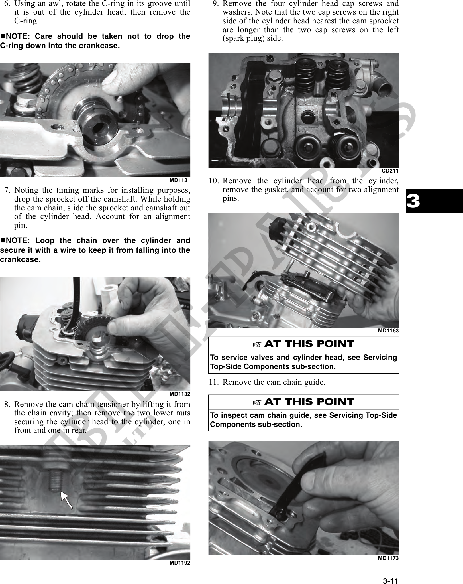
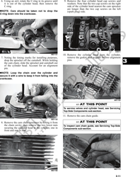
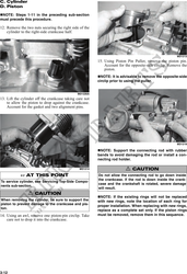
           6. Using an awl, rotate the C-ring in its groove until    9. Remove the four cylinder head cap screws and
    it is out of the cylinder head; then remove the           washers. Note that the two cap screws on the right
    C-ring.                                                   side of the cylinder head nearest the cam sprocket
                                                              are longer than the two cap screws on the left
 NOTE: Care should be taken not to drop the                   (spark plug) side.
C-ring down into the crankcase.


                                                                                                           CD211
                                                MD1131    10. Remove the cylinder head from the cylinder,
 7. Noting the timing marks for installing purposes,          remove the gasket, and account for two alignment
    drop the sprocket off the camshaft. While holding
    the cam chain, slide the sprocket and camshaft out
                                                              pins.
                                                                                                                   3
    of the cylinder head. Account for an alignment
    pin.
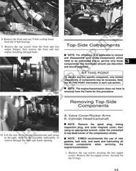
 NOTE: Loop the chain over the cylinder and
secure it with a wire to keep it from falling into the
crankcase.


                                                                                                          MD1163

                                                                         AT THIS POINT
                                                          To service valves and cylinder head, see Servicing
                                                          Top-Side Components sub-section.

                                                          11. Remove the cam chain guide.
                                                MD1132
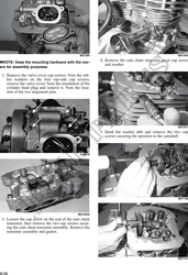
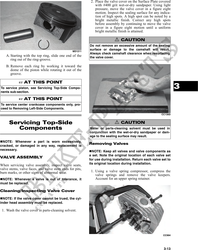
 8. Remove the cam chain tensioner by lifting it from                    AT THIS POINT
    the chain cavity; then remove the two lower nuts      To inspect cam chain guide, see Servicing Top-Side
    securing the cylinder head to the cylinder, one in    Components sub-section.
    front and one in rear.


                                                                                                          MD1173
                                                MD1192


                                                                                                           3-11