2. Remove the heat shield; then remove the gas tank
(see Section 4).
Table of Contents
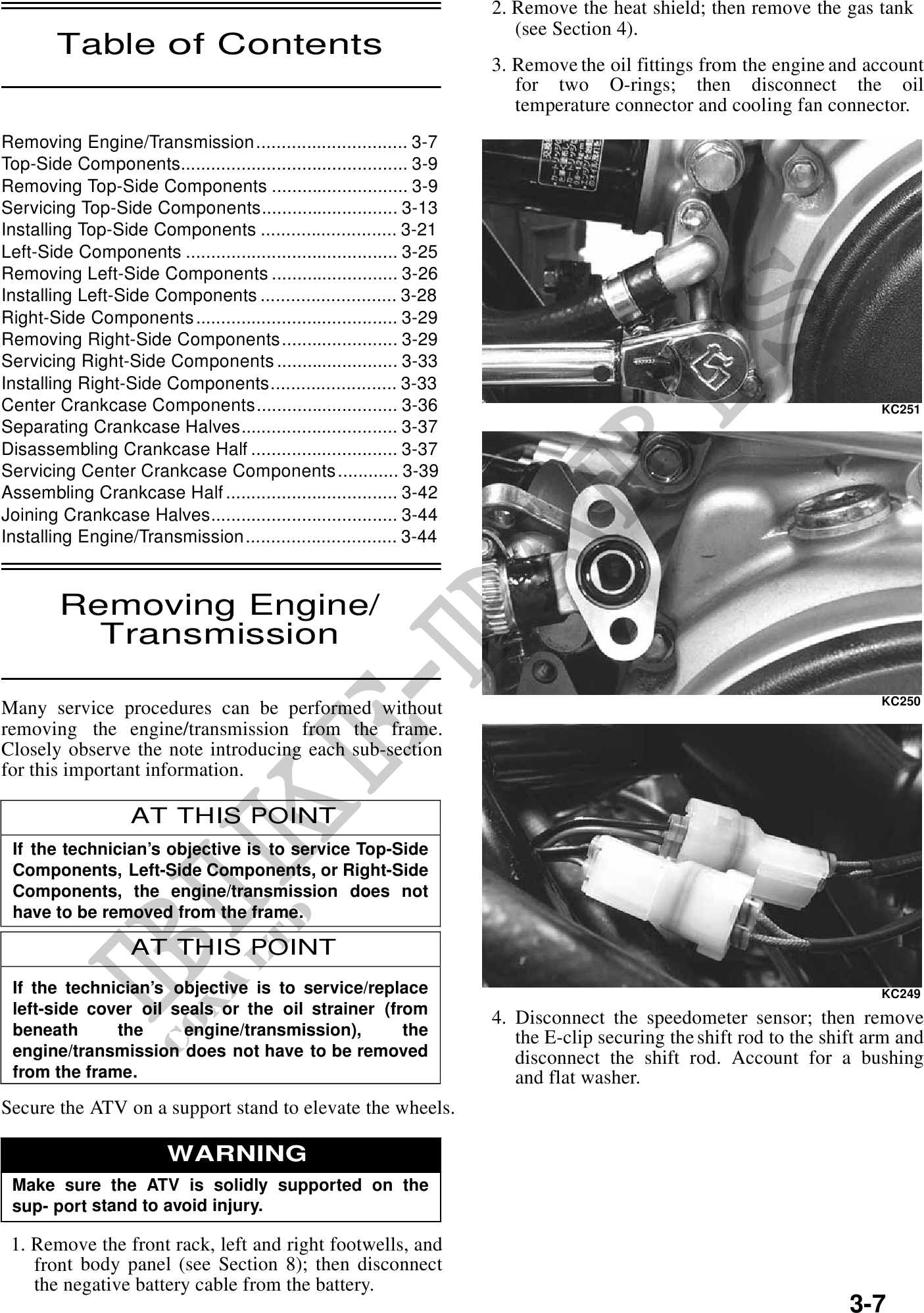
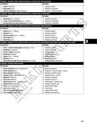
3. Remove the oil fittings from the engine and account
for two O-rings; then disconnect the oil
temperature connector and cooling fan connector.
Removing Engine/Transmission .............................. 3-7
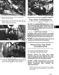
Top-Side Components............................................. 3-9
Removing Top-Side Components ........................... 3-9
Servicing Top-Side Components........................... 3-13
Installing Top-Side Components ........................... 3-21
Left-Side Components .......................................... 3-25
Removing Left-Side Components ......................... 3-26
Installing Left-Side Components ........................... 3-28
Right-Side Components ........................................ 3-29
Removing Right-Side Components ....................... 3-29
Servicing Right-Side Components ........................ 3-33
Installing Right-Side Components......................... 3-33
Center Crankcase Components............................ 3-36 KC251
Separating Crankcase Halves............................... 3-37
Disassembling Crankcase Half ............................. 3-37
Servicing Center Crankcase Components ............ 3-39
Assembling Crankcase Half .................................. 3-42 3
Joining Crankcase Halves..................................... 3-44
Installing Engine/Transmission .............................. 3-44
Removing Engine/
Transmission
KC250
Many service procedures can be performed without
removing the engine/transmission from the frame.
Closely observe the note introducing each sub-section
for this important information.
AT THIS POINT
If the technician's objective is to service Top-Side
Components, Left-Side Components, or Right-Side
Components, the engine/transmission does not
have to be removed from the frame.
AT THIS POINT
If the technician's objective is to service/replace KC249
left-side cover oil seals or the oil strainer (from
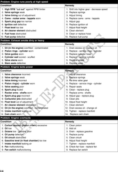
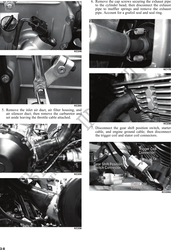
4. Disconnect the speedometer sensor; then remove
beneath the engine/transmission), the the E-clip securing the shift rod to the shift arm and
engine/transmission does not have to be removed disconnect the shift rod. Account for a bushing
from the frame. and flat washer.
Secure the ATV on a support stand to elevate the wheels.
WARNING
Make sure the ATV is solidly supported on the
sup- port stand to avoid injury.
1. Remove the front rack, left and right footwells, and
front body panel (see Section 8); then disconnect
the negative battery cable from the battery.
3-7