mxu 400 Manuel atelier : Page 62

Microfiches
Image preview

Page 60

Image preview

Page 61

Image preview

Page 63

Image preview

Page 64

1 5 10 15 20 25 30 35 40 45 50 55 60 65 70 75 80 85 90 95 100 105 110 115 120 125 130 135 137
                                                         MD1017                                                  MD1060
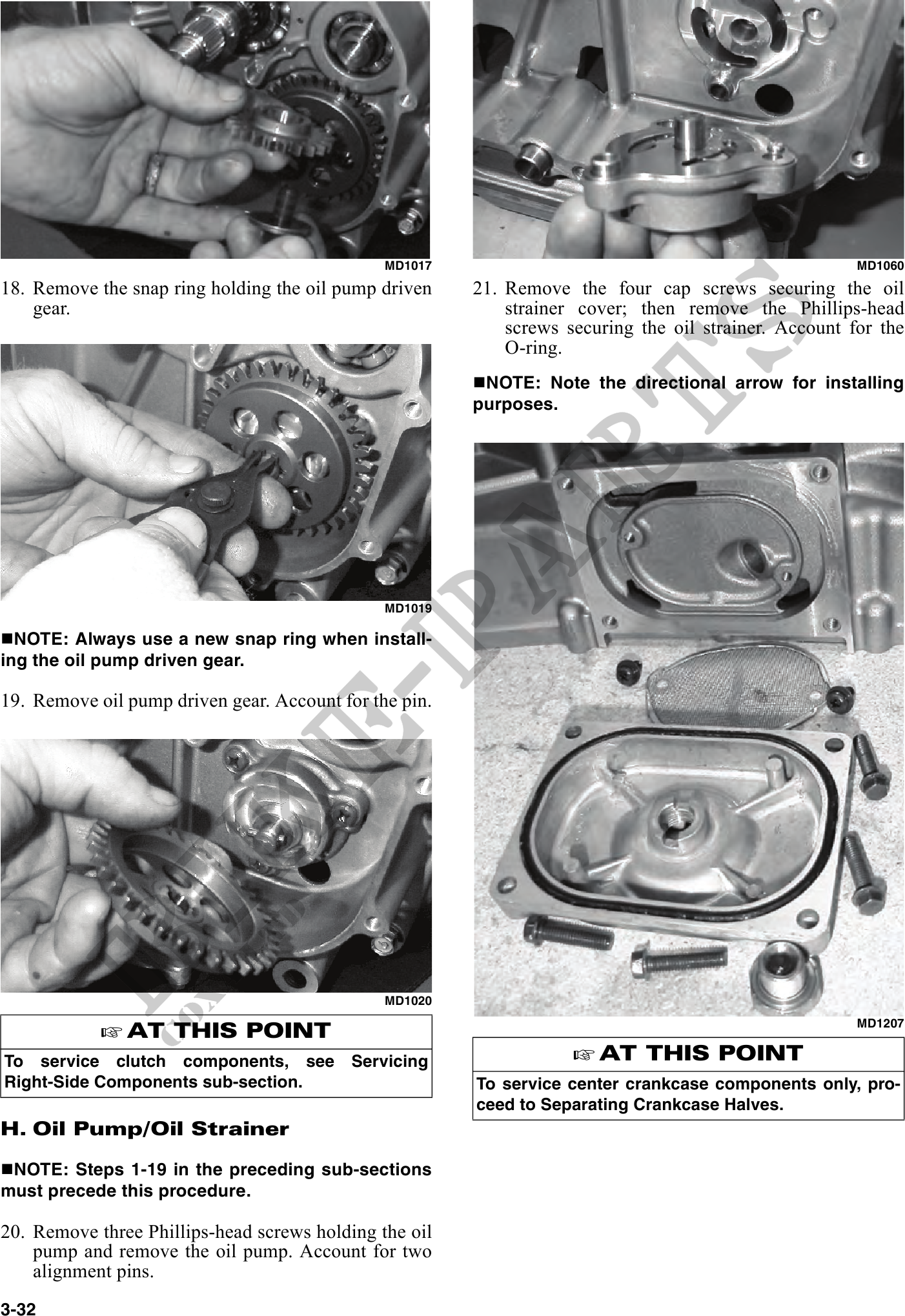
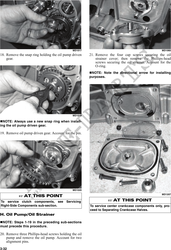
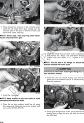
18. Remove the snap ring holding the oil pump driven    21. Remove the four cap screws securing the oil
    gear.                                                   strainer cover; then remove the Phillips-head
                                                            screws securing the oil strainer. Account for the
                                                            O-ring.
                                                         NOTE: Note the directional arrow for installing
                                                        purposes.


                                               MD1019

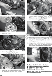
  NOTE: Always use a new snap ring when install-
ing the oil pump driven gear.

19. Remove oil pump driven gear. Account for the pin.


                                               MD1020

               AT THIS POINT                                                                           MD1207


To service clutch components, see          Servicing                   AT THIS POINT
Right-Side Components sub-section.                      To service center crankcase components only, pro-
                                                        ceed to Separating Crankcase Halves.
H. Oil Pump/Oil Strainer

 NOTE: Steps 1-19 in the preceding sub-sections
must precede this procedure.

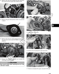
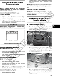
20. Remove three Phillips-head screws holding the oil
    pump and remove the oil pump. Account for two
    alignment pins.
3-32