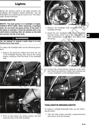
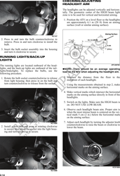
                                Tires                                      Suspension/Shock
                                                                Absorbers/Bushings
TIRE SIZES
                                                            The following suspension system components should
The ATV is equipped with low-pressure tubeless tires        be inspected periodically to ensure proper operation.
of the size and type listed (see Section 1). Do not under
any circumstances substitute tires of a different type or       A. Shock absorber rods not bent, pitted, or damaged.
size.
                                                                B. Rubber damper not cracked, broken, or missing.
                 ! WARNING                                      C. Shock absorber body not damaged, punctured,
Always use the size and type of tires specified.                   or leaking.
Always maintain proper tire inflation pressure.
                                                                D. Shock absorber eyelets not broken, bent, or
TIRE INFLATION PRESSURE                                            cracked.
                                                                E. Shock absorber eyelet bushings not worn, dete-
Front and rear tire inflation pressure should be 0.28              riorated, cracked, or missing.
kg-cm (4.0 psi).
                                                                F. Shock absorber spring not broken or sagging.

  Steering Components
                                                             Nuts/Bolts/Cap Screws
The following steering components should be inspected
periodically to ensure safe and proper operation.           Tighten all nuts, bolts, and cap screws. Make sure riv-
                                                            ets holding components together are tight. Replace all
    A. Handlebar grips not worn, broken, or loose.          loose rivets. Care must be taken that all calibrated
    B. Handlebar not bent, cracked, and has equal and       nuts, bolts, and cap screws are tightened to specifica-
       complete full-left and full-right capability.        tions.

    C. Steering post bearing assembly/bearing housing
       not broken, worn, or binding.
                                                                      Ignition Timing
    D. Ball joints not worn, cracked, or damaged.
    E. Tie rods not bent or cracked.
                                                            The ignition timing cannot be adjusted; however, veri-
    F. Knuckles not worn, cracked, or damaged.              fying ignition timing can aid in troubleshooting other
                                                            components. To verify ignition timing, use the follow-
    G. Cotter pins not damaged or missing.                  ing procedure.
                                                             1. Attach the Timing Light to the spark plug high ten-
                                                                sion lead; then remove the timing inspection plug
       Driveshaft/Coupling                                      from the left-side crankcase cover.
                                                             2. Using the Tachometer, start the engine and run at
                                                                1500 RPM; ignition timing should be 10° BTDC.
The following drive system components should be
inspected periodically to ensure proper operation.           3. Install the timing inspection plug.
    A. Spline lateral movement (slop).                      If ignition timing cannot be verified, the rotor may be
                                                            damaged, the key may be sheared, the trigger coil
    B. Coupling cracked, damaged, or worn.                  bracket may be bent or damaged, or the CDI unit may
                                                            be faulty.


2-12