Testing Engine
Compression
To test engine compression, use the following proce-
dure.
1. Remove the high tension lead from the spark plug.
2. Using compressed air, blow any debris from
around the spark plug.
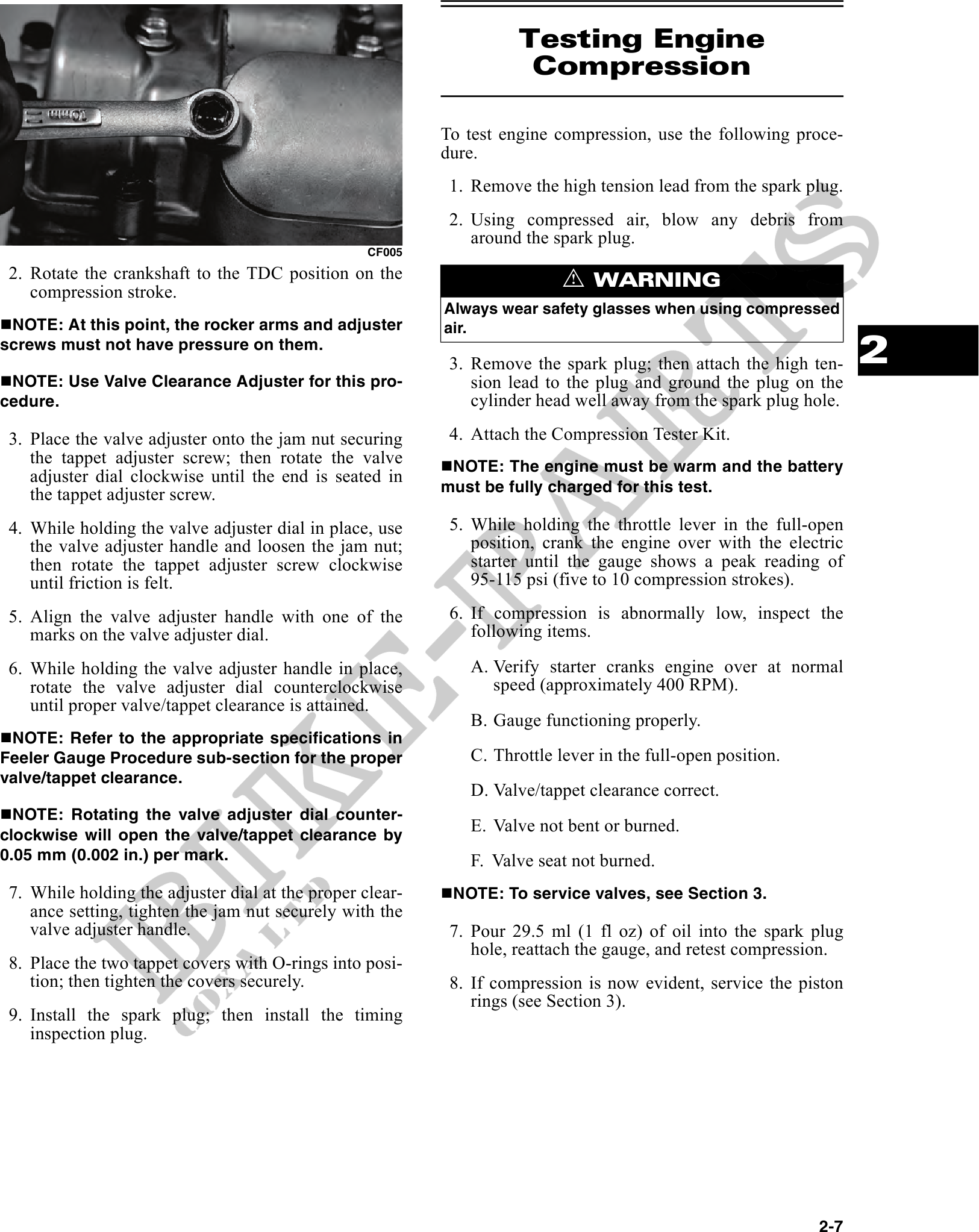
CF005
2. Rotate the crankshaft to the TDC position on the ! WARNING
compression stroke.
Always wear safety glasses when using compressed
NOTE: At this point, the rocker arms and adjuster air.
screws must not have pressure on them.
3. Remove the spark plug; then attach the high ten- 2
NOTE: Use Valve Clearance Adjuster for this pro- sion lead to the plug and ground the plug on the
cedure. cylinder head well away from the spark plug hole.
3. Place the valve adjuster onto the jam nut securing 4. Attach the Compression Tester Kit.
the tappet adjuster screw; then rotate the valve NOTE: The engine must be warm and the battery
adjuster dial clockwise until the end is seated in
the tappet adjuster screw. must be fully charged for this test.
4. While holding the valve adjuster dial in place, use 5. While holding the throttle lever in the full-open
the valve adjuster handle and loosen the jam nut; position, crank the engine over with the electric
then rotate the tappet adjuster screw clockwise starter until the gauge shows a peak reading of
until friction is felt. 95-115 psi (five to 10 compression strokes).
5. Align the valve adjuster handle with one of the 6. If compression is abnormally low, inspect the
marks on the valve adjuster dial. following items.
6. While holding the valve adjuster handle in place, A. Verify starter cranks engine over at normal
rotate the valve adjuster dial counterclockwise speed (approximately 400 RPM).
until proper valve/tappet clearance is attained.
B. Gauge functioning properly.
NOTE: Refer to the appropriate specifications in
Feeler Gauge Procedure sub-section for the proper C. Throttle lever in the full-open position.
valve/tappet clearance.
D. Valve/tappet clearance correct.
NOTE: Rotating the valve adjuster dial counter-
clockwise will open the valve/tappet clearance by
E. Valve not bent or burned.
0.05 mm (0.002 in.) per mark. F. Valve seat not burned.
7. While holding the adjuster dial at the proper clear- NOTE: To service valves, see Section 3.
ance setting, tighten the jam nut securely with the
valve adjuster handle. 7. Pour 29.5 ml (1 fl oz) of oil into the spark plug
hole, reattach the gauge, and retest compression.
8. Place the two tappet covers with O-rings into posi-
tion; then tighten the covers securely. 8. If compression is now evident, service the piston
rings (see Section 3).
9. Install the spark plug; then install the timing
inspection plug.
2-7