4. LUBRICATION SYSTEM MXU 250R/300R
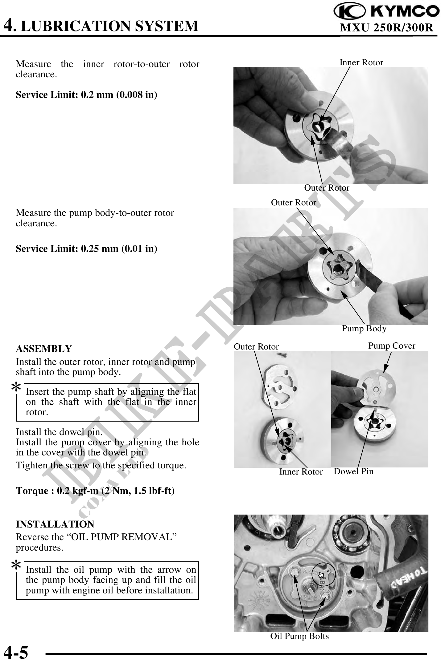
Measure the inner rotor-to-outer rotor Inner Rotor
clearance.
Service Limit: 0.2 mm (0.008 in)
Outer Rotor
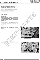
Outer Rotor
Measure the pump body-to-outer rotor
clearance.
Service Limit: 0.25 mm (0.01 in)
Pump Body
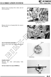
ASSEMBLY Outer Rotor Pump Cover
Install the outer rotor, inner rotor and pump
shaft into the pump body.
Insert the pump shaft by aligning the flat
on the shaft with the flat in the inner
rotor.
Install the dowel pin.
Install the pump cover by aligning the hole
in the cover with the dowel pin.
Tighten the screw to the specified torque.
Inner Rotor Dowel Pin
Torque : 0.2 kgf-m (2 Nm, 1.5 lbf-ft)
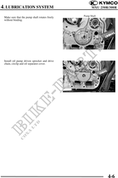
INSTALLATION
Reverse the "OIL PUMP REMOVAL"
procedures.
Install the oil pump with the arrow on
the pump body facing up and fill the oil
pump with engine oil before installation.
Oil Pump Bolts
4-5