7. CYLINDER HEAD/VALVES AGILITY 125
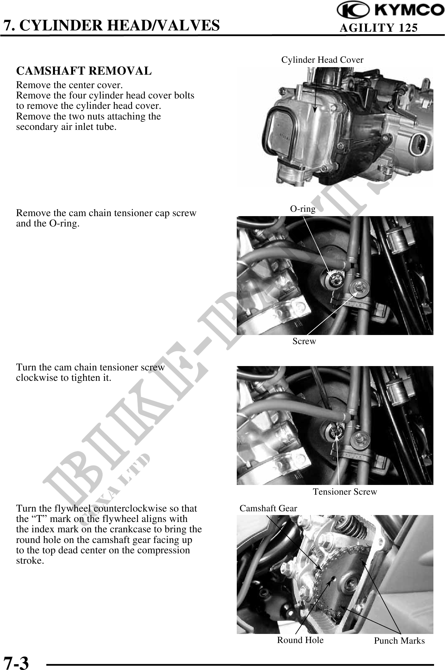
Cylinder Head Cover
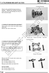
CAMSHAFT REMOVAL
Remove the center cover.
Remove the four cylinder head cover bolts
to remove the cylinder head cover.
Remove the two nuts attaching the
secondary air inlet tube.
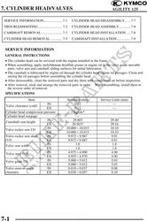
Remove the cam chain tensioner cap screw O-ring
and the O-ring.
Screw
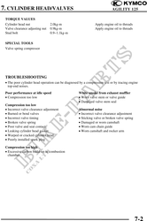
Turn the cam chain tensioner screw
clockwise to tighten it.
Tensioner Screw
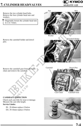
Turn the flywheel counterclockwise so that Camshaft Gear
the "T" mark on the flywheel aligns with
the index mark on the crankcase to bring the
round hole on the camshaft gear facing up
to the top dead center on the compression
stroke.
Round Hole Punch Marks
7-3