Mon Panier

| Désignation | Référence | Qté |
|---|
| Désignation | Référence | Qté |
|---|
KC149A KC128
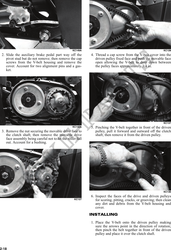
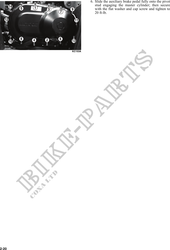
2. Slide the auxiliary brake pedal part way off the 4. Thread a cap screw from the V-belt cover into the
pivot stud but do not remove; then remove the cap driven pulley fixed face and push the movable face
screws from the V-belt housing and remove the open allowing the V-belt to drop down between
cover. Account for two alignment pins and a gas- the pulley faces approximately 3/4 in.
ket.
KC137
KC142A 5. Pinching the V-belt together in front of the driven
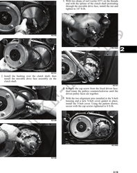
3. Remove the nut securing the movable drive face to pulley, pull it forward and outward off the clutch
the clutch shaft; then remove the movable drive shaft; then remove it from the driven pulley.
face assembly being careful not to let the roller fall
out. Account for a bushing.
KC136
6. Inspect the faces of the drive and driven pulleys
KC127 for scoring, pitting, cracks, or grooving; then clean
any dirt and debris from the V-belt housing and
cover.
INSTALLING
1. Place the V-belt onto the driven pulley making
sure the arrows point in the direction of rotation;
then pinch the belt together in front of the driven
pulley and place it over the clutch shaft.
2-18