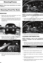
KC308 PR287A
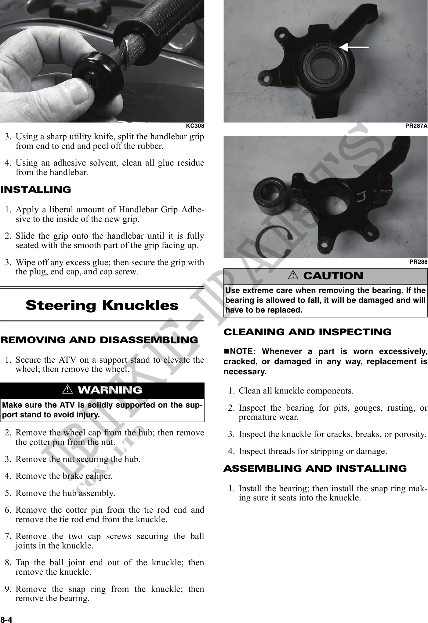
3. Using a sharp utility knife, split the handlebar grip
from end to end and peel off the rubber.
4. Using an adhesive solvent, clean all glue residue
from the handlebar.
INSTALLING
1. Apply a liberal amount of Handlebar Grip Adhe-
sive to the inside of the new grip.
2. Slide the grip onto the handlebar until it is fully
seated with the smooth part of the grip facing up.
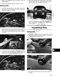
3. Wipe off any excess glue; then secure the grip with PR288
the plug, end cap, and cap screw.
! CAUTION
Use extreme care when removing the bearing. If the
Steering Knuckles
bearing is allowed to fall, it will be damaged and will
have to be replaced.
CLEANING AND INSPECTING
REMOVING AND DISASSEMBLING
NOTE: Whenever a part is worn excessively,
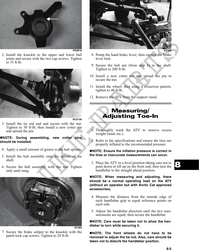
1. Secure the ATV on a support stand to elevate the cracked, or damaged in any way, replacement is
wheel; then remove the wheel. necessary.
! WARNING 1. Clean all knuckle components.
Make sure the ATV is solidly supported on the sup- 2. Inspect the bearing for pits, gouges, rusting, or
port stand to avoid injury. premature wear.
2. Remove the wheel cap from the hub; then remove 3. Inspect the knuckle for cracks, breaks, or porosity.
the cotter pin from the nut.
4. Inspect threads for stripping or damage.
3. Remove the nut securing the hub.
ASSEMBLING AND INSTALLING
4. Remove the brake caliper.
5. Remove the hub assembly. 1. Install the bearing; then install the snap ring mak-
ing sure it seats into the knuckle.
6. Remove the cotter pin from the tie rod end and
remove the tie rod end from the knuckle.
7. Remove the two cap screws securing the ball
joints in the knuckle.
8. Tap the ball joint end out of the knuckle; then
remove the knuckle.
9. Remove the snap ring from the knuckle; then
remove the bearing.
8-4