mxu 400 Manuel atelier : Page 123

Microfiches
Image preview

Page 121

Image preview

Page 122

Image preview

Page 124

Image preview

Page 125

1 5 10 15 20 25 30 35 40 45 50 55 60 65 70 75 80 85 90 95 100 105 110 115 120 125 130 135 137
          7. Inspect the handlebar tube for cracks, wear, or       4. Place the handlebar and caps in place on the steer-
   unusual bends.                                           ing post and with the handlebar correctly posi-
                                                            tioned, tighten the cap screws to 20 ft-lb.
8. Inspect the handlebar grips for damage or wear.
INSTALLING

1. Install the steering post into the frame and secure
   the lower end in the bearing with a flat washer and
   cap screw. Tighten to 40 ft-lb.


                                                                                                            KC0058
                                                         5. Install the steering post cover; then install the front
                                                            body panel/fender (see Front Body Panel/Fender
                                                            in this section).


                                               KC184B             Handlebar Grip
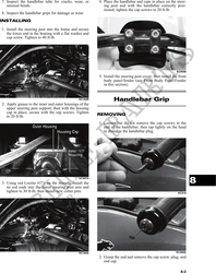
2. Apply grease to the inner and outer housings of the
   upper steering post support; then with the housing
   cap in place, secure with the cap screws. Tighten
   to 20 ft-lb.                                          REMOVING

                                                         1. Loosen but do not remove the cap screws in the
                                                            end of the handlebar; then tap lightly on the head
                                                            to dislodge the handlebar plug.


                                               KC307A
3. Using red Loctite #271 on the threads, install the                                                                 8
   tie rod ends into the lower steering post arm and
   tighten to 30 ft-lb; then install new cotter pins.                                                        KC310


                                               KC184A                                                       KC309A
                                                         2. Grasp the end and remove the cap screw, plug, and
                                                            end cap.

                                                                                                               8-3