mxu 400 Manuel atelier : Page 111

Microfiches
Image preview

Page 109

Image preview

Page 110

Image preview

Page 112

Image preview

Page 113

1 5 10 15 20 25 30 35 40 45 50 55 60 65 70 75 80 85 90 95 100 105 110 115 120 125 130 135 137
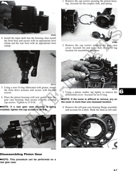
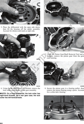
                                                                       1. Remove the cap screws securing the pinion hous-
                                                                ing. Account for the coupler, fork, and spring.


                                                   KX222
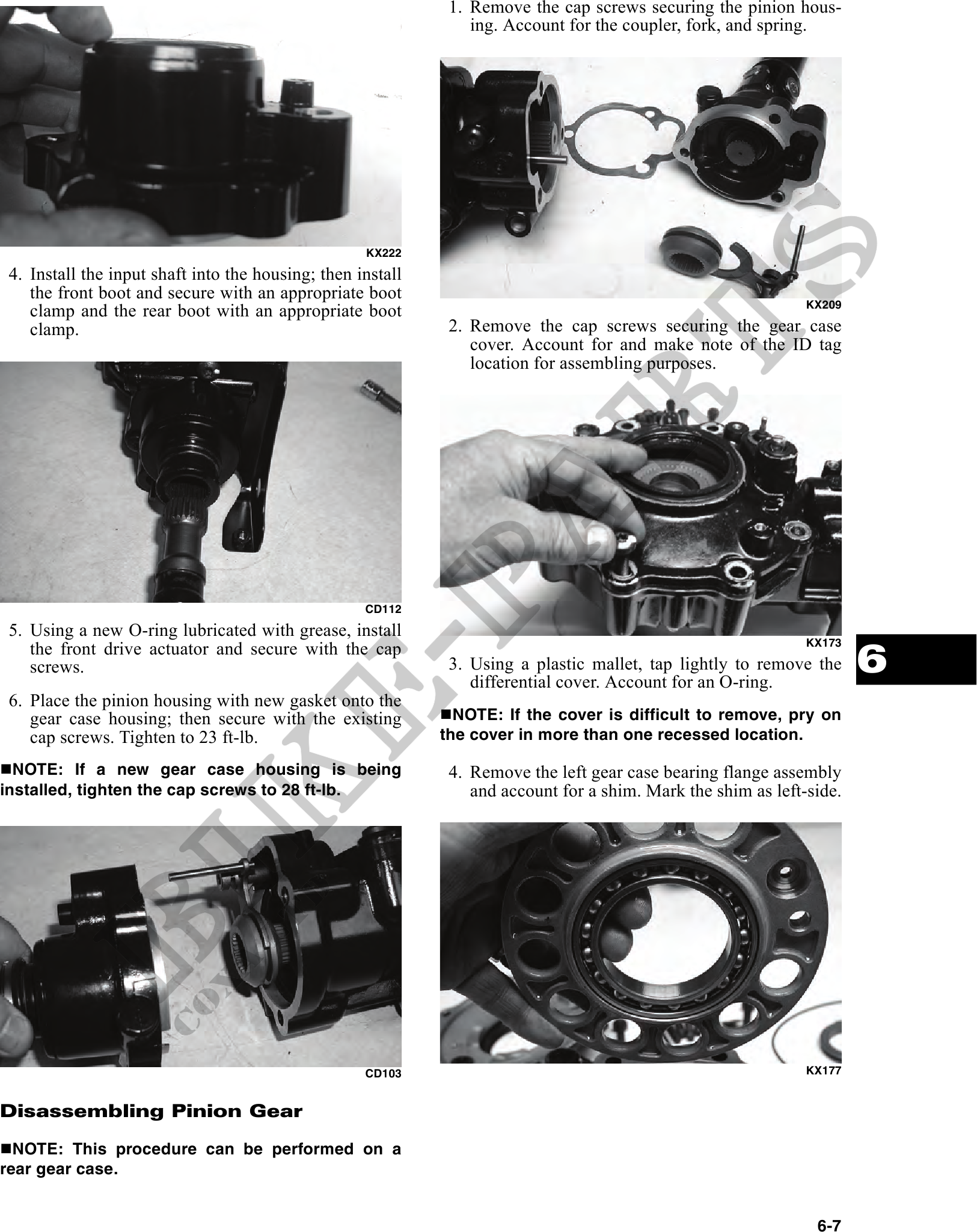
4. Install the input shaft into the housing; then install
   the front boot and secure with an appropriate boot
   clamp and the rear boot with an appropriate boot                                                           KX209

   clamp.                                                    2. Remove the cap screws securing the gear case
                                                                cover. Account for and make note of the ID tag
                                                                location for assembling purposes.


                                                   CD112
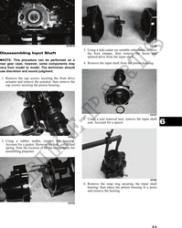
5. Using a new O-ring lubricated with grease, install
   the front drive actuator and secure with the cap
                                                                                                                      6
                                                                                                              KX173

   screws.                                                   3. Using a plastic mallet, tap lightly to remove the
                                                                differential cover. Account for an O-ring.
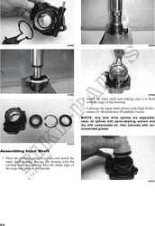
6. Place the pinion housing with new gasket onto the
   gear case housing; then secure with the existing           NOTE: If the cover is difficult to remove, pry on
   cap screws. Tighten to 23 ft-lb.                         the cover in more than one recessed location.

  NOTE: If a new gear case housing is being                  4. Remove the left gear case bearing flange assembly
installed, tighten the cap screws to 28 ft-lb.                  and account for a shim. Mark the shim as left-side.


                                                   CD103                                                      KX177


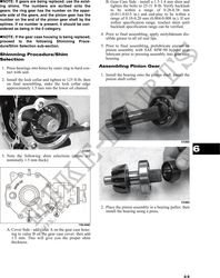
Disassembling Pinion Gear

  NOTE: This procedure can be performed on a
rear gear case.


                                                                                                               6-7