Mon Panier

| Désignation | Référence | Qté |
|---|
| Désignation | Référence | Qté |
|---|
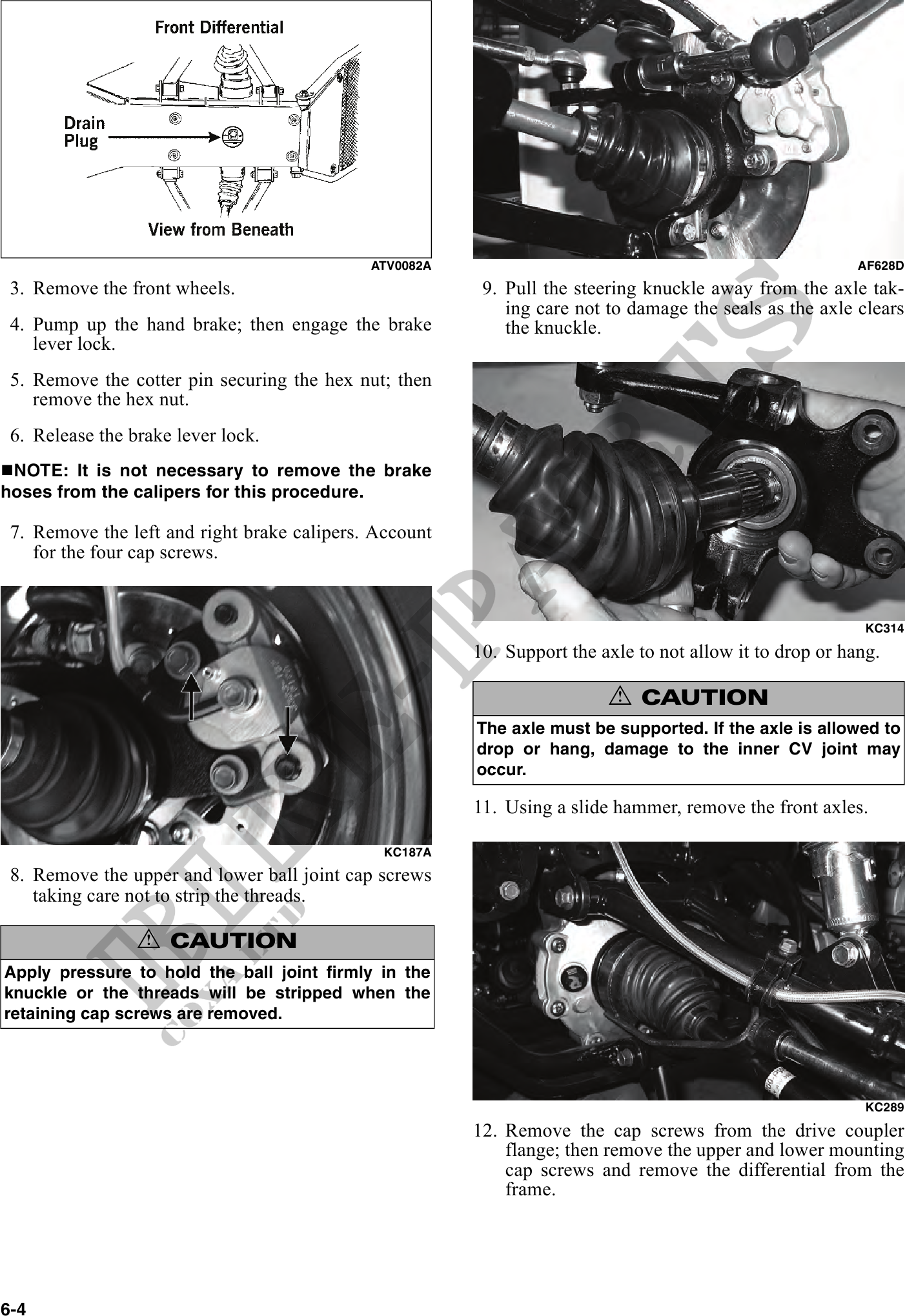
ATV0082A AF628D
3. Remove the front wheels. 9. Pull the steering knuckle away from the axle tak-
ing care not to damage the seals as the axle clears
4. Pump up the hand brake; then engage the brake the knuckle.
lever lock.
5. Remove the cotter pin securing the hex nut; then
remove the hex nut.
6. Release the brake lever lock.
NOTE: It is not necessary to remove the brake
hoses from the calipers for this procedure.
7. Remove the left and right brake calipers. Account
for the four cap screws.
KC314
10. Support the axle to not allow it to drop or hang.
! CAUTION
The axle must be supported. If the axle is allowed to
drop or hang, damage to the inner CV joint may
occur.
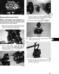
11. Using a slide hammer, remove the front axles.
KC187A
8. Remove the upper and lower ball joint cap screws
taking care not to strip the threads.
! CAUTION
Apply pressure to hold the ball joint firmly in the
knuckle or the threads will be stripped when the
retaining cap screws are removed.
KC289
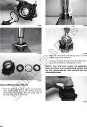
12. Remove the cap screws from the drive coupler
flange; then remove the upper and lower mounting
cap screws and remove the differential from the
frame.
6-4