Mon Panier

| Désignation | Référence | Qté |
|---|
| Désignation | Référence | Qté |
|---|
KC294A KC295A
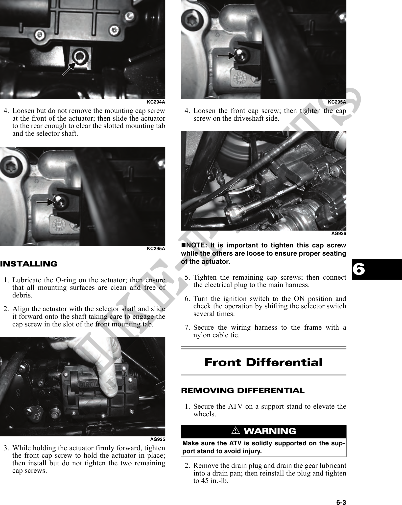
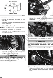
4. Loosen but do not remove the mounting cap screw 4. Loosen the front cap screw; then tighten the cap
at the front of the actuator; then slide the actuator screw on the driveshaft side.
to the rear enough to clear the slotted mounting tab
and the selector shaft.
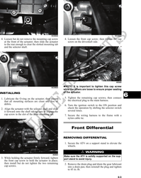
AG926
KC295A
NOTE: It is important to tighten this cap screw
while the others are loose to ensure proper seating
of the actuator.
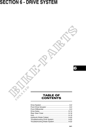
INSTALLING
1. Lubricate the O-ring on the actuator; then ensure 5. Tighten the remaining cap screws; then connect
6
that all mounting surfaces are clean and free of the electrical plug to the main harness.
debris. 6. Turn the ignition switch to the ON position and
2. Align the actuator with the selector shaft and slide check the operation by shifting the selector switch
it forward onto the shaft taking care to engage the several times.
cap screw in the slot of the front mounting tab. 7. Secure the wiring harness to the frame with a
nylon cable tie.
Front Differential
REMOVING DIFFERENTIAL
1. Secure the ATV on a support stand to elevate the
wheels.
! WARNING
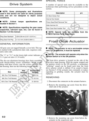
AG925
Make sure the ATV is solidly supported on the sup-
3. While holding the actuator firmly forward, tighten port stand to avoid injury.
the front cap screw to hold the actuator in place;
then install but do not tighten the two remaining 2. Remove the drain plug and drain the gear lubricant
cap screws. into a drain pan; then reinstall the plug and tighten
to 45 in.-lb.
6-3