vitality 50 2t 4t 1 Manuel atelier : Page 76

Microfiches
Image preview

Page 74

Image preview

Page 75

Image preview

Page 77

Image preview

Page 78

1 5 10 15 20 25 30 35 40 45 50 55 60 65 70 75 80 85 90 95 100 105 110 115 120 125 130 135 140 145 150 155 160 165 170 175 180 185 190 195 200 205 210 215 220 225 230 235 240 245 250 255 260 265 270 273
          4. LUBRICATION SYSTEM                                                 VITALITY 50
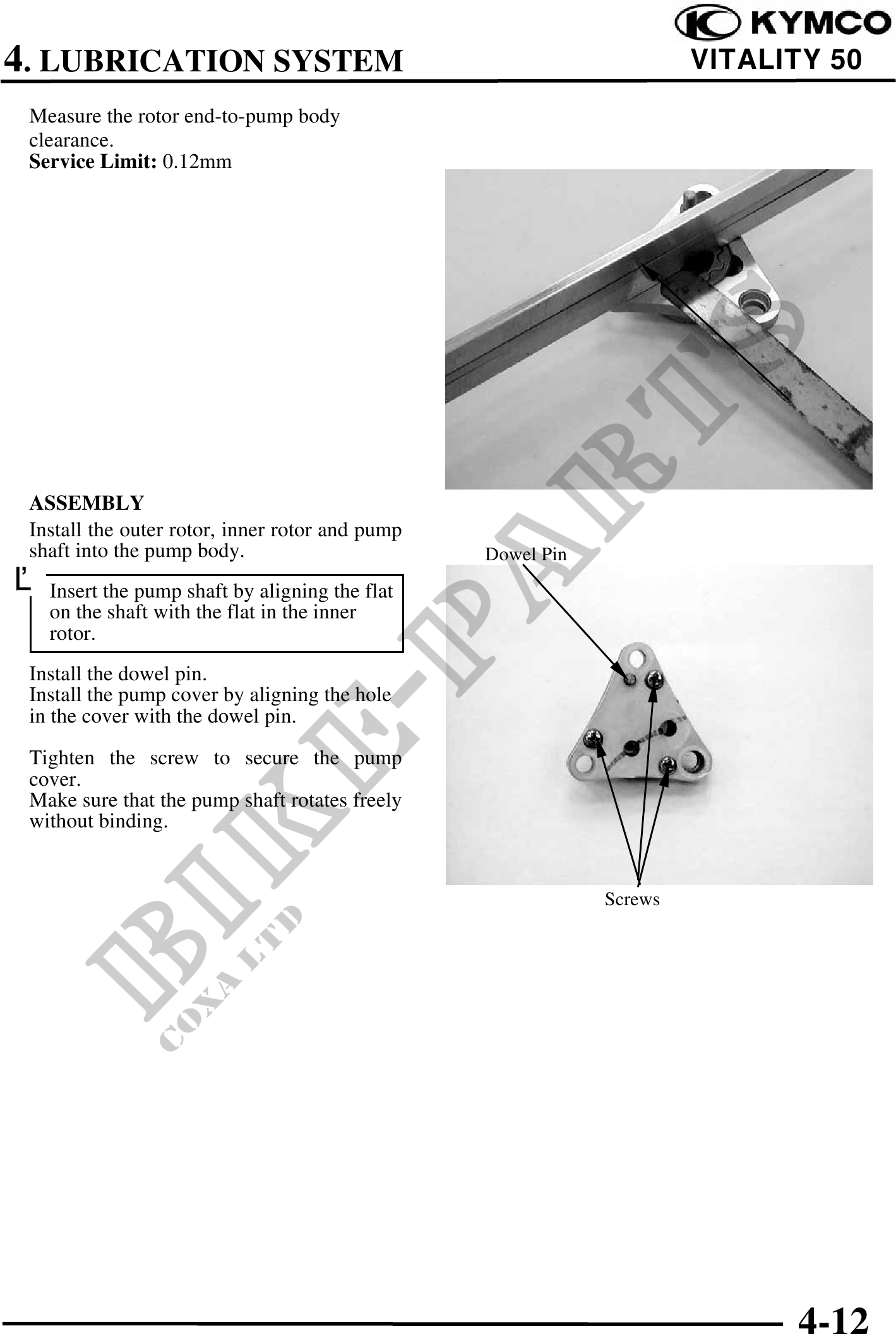
 Measure the rotor end-to-pump body
 clearance.
 Service Limit: 0.12mm


                                                                        Inner Rotor


 ASSEMBLY
 Install the outer rotor, inner rotor and pump
 shaft into the pump body.                       Dowel Pin
 Insert the pump shaft by aligning the flat
    on the shaft with the flat in the inner
    rotor.
 Install the dowel pin.
 Install the pump cover by aligning the hole
 in the cover with the dowel pin.

 Tighten the screw to secure the pump
 cover.
 Make sure that the pump shaft rotates freely
 without binding.


                                                             Screws


                                                                                4-12