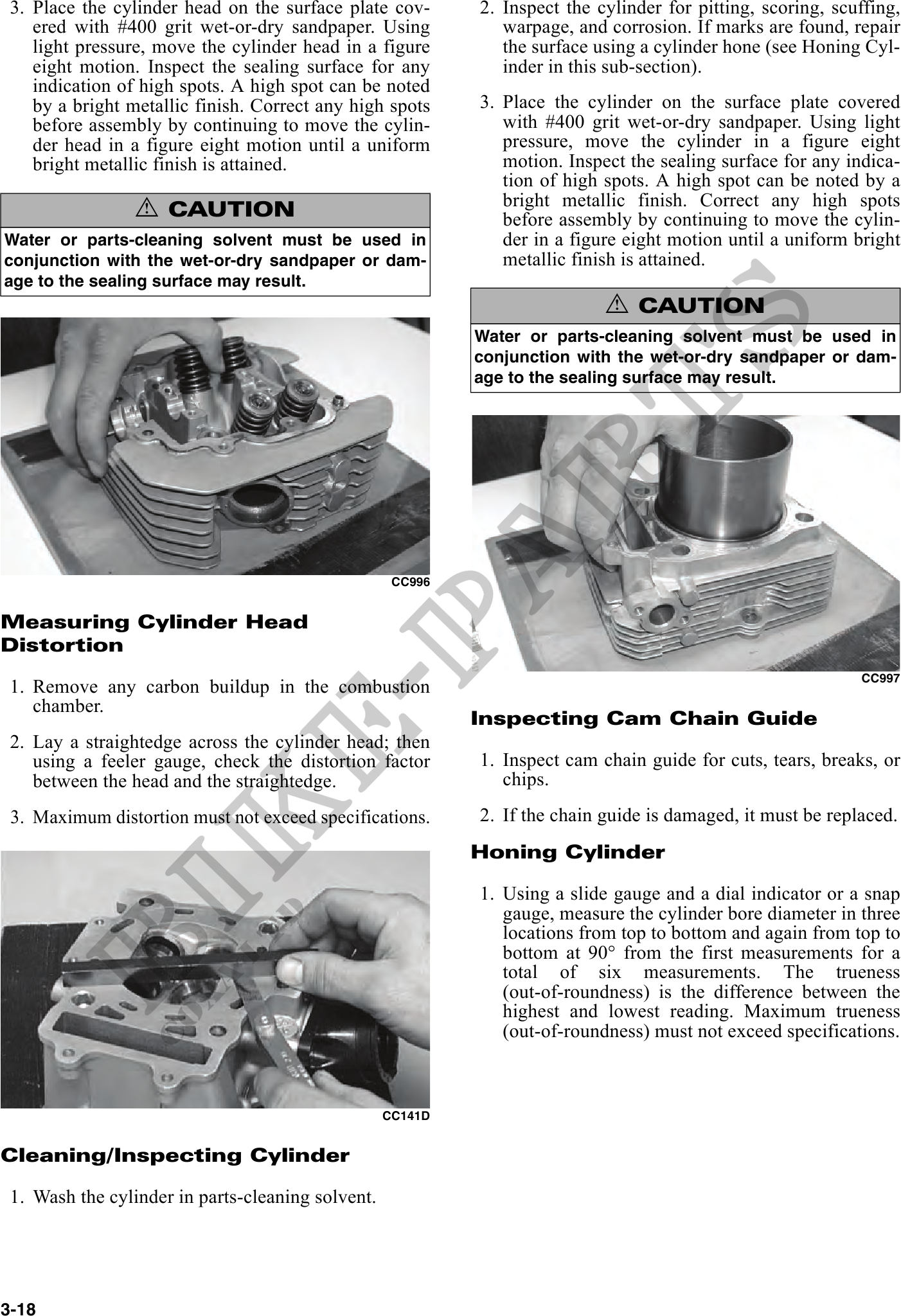
3. Place the cylinder head on the surface plate cov- 2. Inspect the cylinder for pitting, scoring, scuffing,
ered with #400 grit wet-or-dry sandpaper. Using warpage, and corrosion. If marks are found, repair
light pressure, move the cylinder head in a figure the surface using a cylinder hone (see Honing Cyl-
eight motion. Inspect the sealing surface for any inder in this sub-section).
indication of high spots. A high spot can be noted
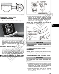
by a bright metallic finish. Correct any high spots 3. Place the cylinder on the surface plate covered
before assembly by continuing to move the cylin- with #400 grit wet-or-dry sandpaper. Using light
der head in a figure eight motion until a uniform pressure, move the cylinder in a figure eight
bright metallic finish is attained. motion. Inspect the sealing surface for any indica-
tion of high spots. A high spot can be noted by a
bright metallic finish. Correct any high spots
! CAUTION before assembly by continuing to move the cylin-
Water or parts-cleaning solvent must be used in der in a figure eight motion until a uniform bright
conjunction with the wet-or-dry sandpaper or dam- metallic finish is attained.
age to the sealing surface may result.
! CAUTION
Water or parts-cleaning solvent must be used in
conjunction with the wet-or-dry sandpaper or dam-
age to the sealing surface may result.
CC996
Measuring Cylinder Head
Distortion
CC997
1. Remove any carbon buildup in the combustion
chamber.
Inspecting Cam Chain Guide
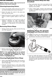
2. Lay a straightedge across the cylinder head; then
using a feeler gauge, check the distortion factor 1. Inspect cam chain guide for cuts, tears, breaks, or
between the head and the straightedge. chips.
3. Maximum distortion must not exceed specifications. 2. If the chain guide is damaged, it must be replaced.
Honing Cylinder
1. Using a slide gauge and a dial indicator or a snap
gauge, measure the cylinder bore diameter in three
locations from top to bottom and again from top to
bottom at 90° from the first measurements for a
total of six measurements. The trueness
(out-of-roundness) is the difference between the
highest and lowest reading. Maximum trueness
(out-of-roundness) must not exceed specifications.
CC141D
Cleaning/Inspecting Cylinder
1. Wash the cylinder in parts-cleaning solvent.
3-18