4. Inspect the banjo-fitting and bolt for cracks and
deterioration and the condition of the fittings
Hand Brake Lever/ (threaded and compression).
Master Cylinder INSTALLING
Assembly
1. Position the brake housing on the handlebar.
Secure with clamp screws; then tighten securely.
NOTE: The master cylinder is a non-serviceable
component; it must be replaced as an assembly.
2. Using two new crush washers, connect the
banjo-fitting to the master cylinder; then secure
with the banjo-fitting bolt. Tighten to 20 ft-lb.
REMOVING
3. Bleed the brake system (see Section 2).
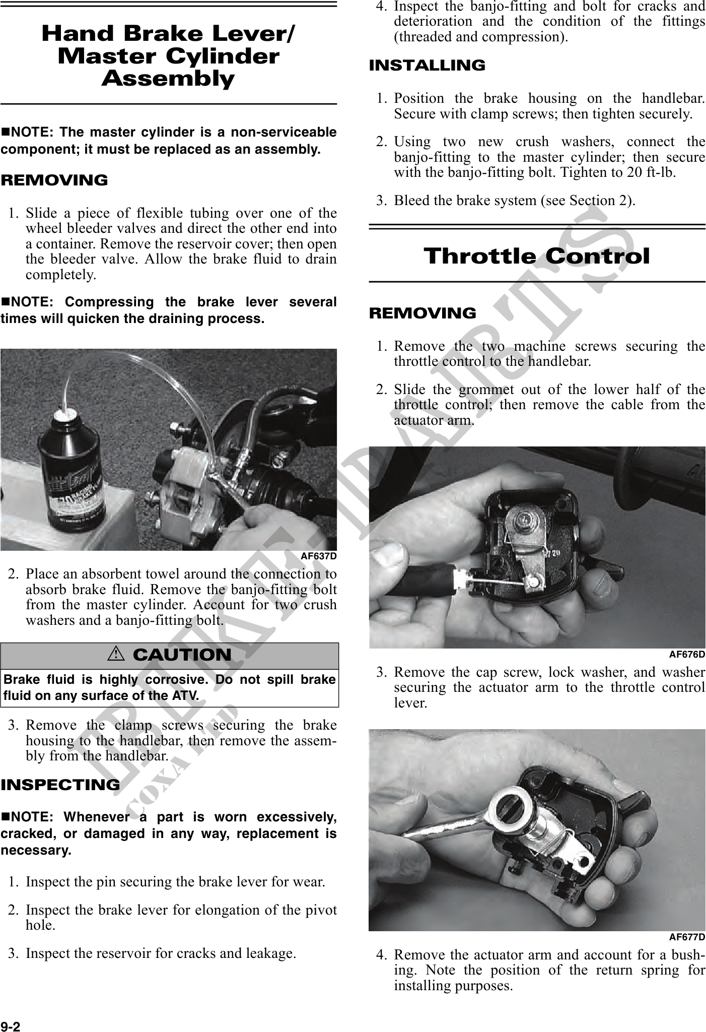
1. Slide a piece of flexible tubing over one of the
wheel bleeder valves and direct the other end into
a container. Remove the reservoir cover; then open
the bleeder valve. Allow the brake fluid to drain Throttle Control
completely.
NOTE: Compressing the brake lever several
times will quicken the draining process. REMOVING
1. Remove the two machine screws securing the
throttle control to the handlebar.
2. Slide the grommet out of the lower half of the
throttle control; then remove the cable from the
actuator arm.
AF637D
2. Place an absorbent towel around the connection to
absorb brake fluid. Remove the banjo-fitting bolt
from the master cylinder. Account for two crush
washers and a banjo-fitting bolt.
! CAUTION AF676D
Brake fluid is highly corrosive. Do not spill brake
3. Remove the cap screw, lock washer, and washer
fluid on any surface of the ATV.
securing the actuator arm to the throttle control
lever.
3. Remove the clamp screws securing the brake
housing to the handlebar, then remove the assem-
bly from the handlebar.
INSPECTING
NOTE: Whenever a part is worn excessively,
cracked, or damaged in any way, replacement is
necessary.
1. Inspect the pin securing the brake lever for wear.
2. Inspect the brake lever for elongation of the pivot
hole.
AF677D
3. Inspect the reservoir for cracks and leakage. 4. Remove the actuator arm and account for a bush-
ing. Note the position of the return spring for
installing purposes.
9-2