DOWNTOWN 125i
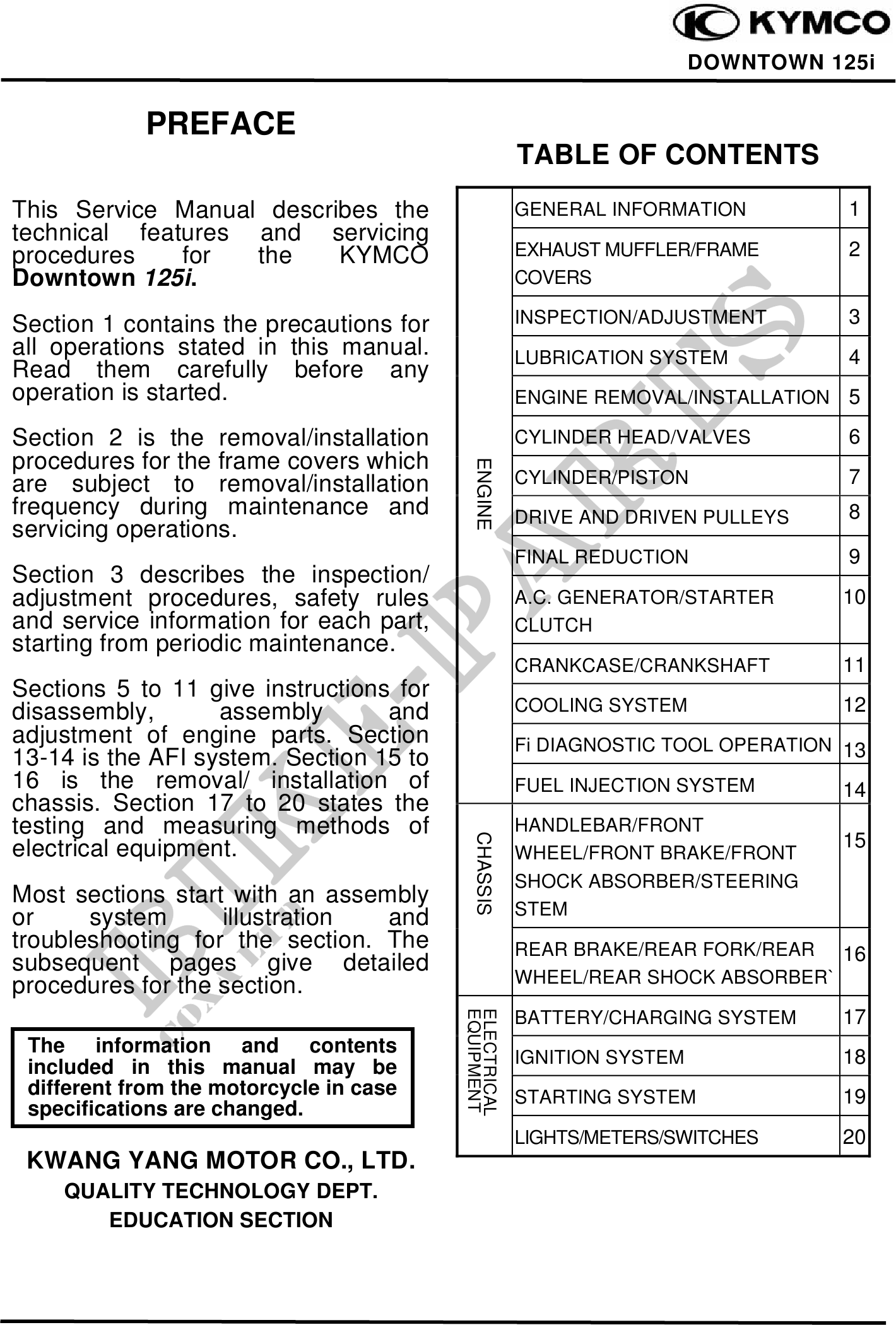
PREFACE
TABLE OF CONTENTS
This Service Manual describes the GENERAL INFORMATION 1
technical features and servicing
procedures for the KYMCO EXHAUST MUFFLER/FRAME 2
Downtown 125i. COVERS
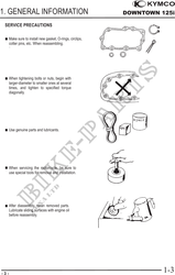
Section 1 contains the precautions for INSPECTION/ADJUSTMENT 3
all operations stated in this manual. LUBRICATION SYSTEM 4
Read them carefully before any
operation is started. ENGINE REMOVAL/INSTALLATION 5
Section 2 is the removal/installation CYLINDER HEAD/VALVES 6
procedures for the frame covers which
ENGINE
are subject to removal/installation CYLINDER/PISTON 7
frequency during maintenance and DRIVE AND DRIVEN PULLEYS 8
servicing operations.
FINAL REDUCTION 9
Section 3 describes the inspection/
adjustment procedures, safety rules A.C. GENERATOR/STARTER 10
and service information for each part, CLUTCH
starting from periodic maintenance.
CRANKCASE/CRANKSHAFT 11
Sections 5 to 11 give instructions for
disassembly, assembly and COOLING SYSTEM 12
adjustment of engine parts. Section Fi DIAGNOSTIC TOOL OPERATION 13
13-14 is the AFI system. Section 15 to
16 is the removal/ installation of FUEL INJECTION SYSTEM 14
chassis. Section 17 to 20 states the
testing and measuring methods of HANDLEBAR/FRONT
CHASSIS
electrical equipment. 15
WHEEL/FRONT BRAKE/FRONT
SHOCK ABSORBER/STEERING
Most sections start with an assembly
or system illustration and STEM
troubleshooting for the section. The REAR BRAKE/REAR FORK/REAR 16
subsequent pages give detailed
procedures for the section. WHEEL/REAR SHOCK ABSORBER`
EQUIPMENT
ELECTRICAL
BATTERY/CHARGING SYSTEM 17
The information and contents
included in this manual may be IGNITION SYSTEM 18
different from the motorcycle in case STARTING SYSTEM 19
specifications are changed.
LIGHTS/METERS/SWITCHES 20
KWANG YANG MOTOR CO., LTD.
QUALITY TECHNOLOGY DEPT.
EDUCATION SECTION