20. LIGHTS/SWITCHES MXU 500 IRS
FUEL UNIT
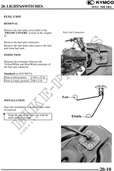
REMOVAL
Remove the fuel tank cover (refer to the
"FRAME COVERS" section in the chapter Fuel Unit Connectors
2).
Remove the fuel unit connectors.
Remove the four bolts, then remove the fuel
unit from fuel tank.
INSPECTION
Measure the resistance between the
Yellow/White and Blue/White terminals of
the fuel unit connector.
Standard (at 20°C/68°F):
Float at full position 1100 33
Float at empty position 100 3
INSTALLATION
Fuel unit installation is in the reverse order
of removal.
Align the tab on the fuel unit with the
mark on the fuel tank.
20-10