6. CYLINDER HEAD/VALVES STRYKER 125/150
SERVICE INFORMATION
GENERAL INSTRUCTIONS
· A engine stand or floor jack is required to support and maneuver the engine.
· A engine stand or floor jack is required to support and maneuver the engine.
· The following parts can be serviced with the engine installed in the frame:
Cylinder head/valves (Section 6)
Cylinder/piston (Section 7)
Starter motor/generator/left crankcase cover/starter clutch/camshaft (Section 8)
Clutch/gear shift mechanism (Section 9)
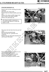
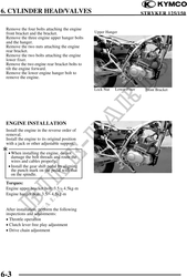
· When removing and installing the engine, do not use a hammer or screw driver to strike or pry
the engine.
· Do not damage the crankcase mating surfaces and clean off all gasket materials from the mating
surfaces.
· After crankcase assembly, check that the transmission system operates smoothly.
· After engine installation, start the engine and check that the lubrication system is normal.
TORQUE VALUES
Engine upper bracket bolt 3.54.5kg-m
Engine hanger bolt 3.54.5kg-m
Drive gear lock bolt 0.81.2kg-m
Exhaust muffler hanger lock bolt 2.43.0kg-m
Rear fork pivot nut 5.56.5kg-m
Exhaust muffler joint lock nut 0.81.2kg-m
6-1