stryker 125 Manuel atelier : Page 142

Microfiches
Image preview

Page 140

Image preview

Page 141

Image preview

Page 143

Image preview

Page 144

1 5 10 15 20 25 30 35 40 45 50 55 60 65 70 75 80 85 90 95 100 105 110 115 120 125 130 135 140 145 150 155 160 165 170 175 180 185 190 195 200 205 210 215 220 225 230 233
          11. FUEL SYSTEM                                                       STRYKER 125/150
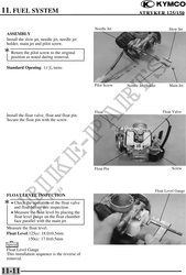

                                                 Needle Jet                           Slow Jet
 ASSEMBLY
 Install the slow jet, needle jet, needle jet
 holder, main jet and pilot screw.
 Return the pilot screw to the original
    position as noted during removal.

 Standard Opening: 11/4 turns


                                                 Pilot Screw   Needle Jet Holder       Main Jet


                                                 Float                             Float Valve
 Install the float valve, float and float pin.
 Secure the float pin with the screw.


                                                 Float Pin                              Screw


                                                                               Float Level Gauge
 FLOAT LEVEL INSPECTION
 · Check the operation of the float valve
      and float before this inspection.
    · Measure the float level by placing the
      float level gauge on the float chamber
      face parallel with the main jet.
 Measure the float level.
 Float Level:125cc: 18.00.5mm
             150cc: 17.00.5mm
 Special
 Float Level Gauge
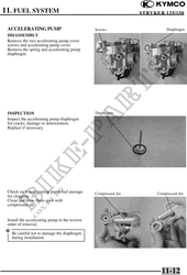
 This installation sequence is the reverse of
 removal.


11-11