15. BATTERY/CHARGING SYSTEM/
A.C. GENERATOR ATV 50
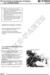
PERFORMANCE TEST
Warm up the engine.
Open the seat and battery cover.
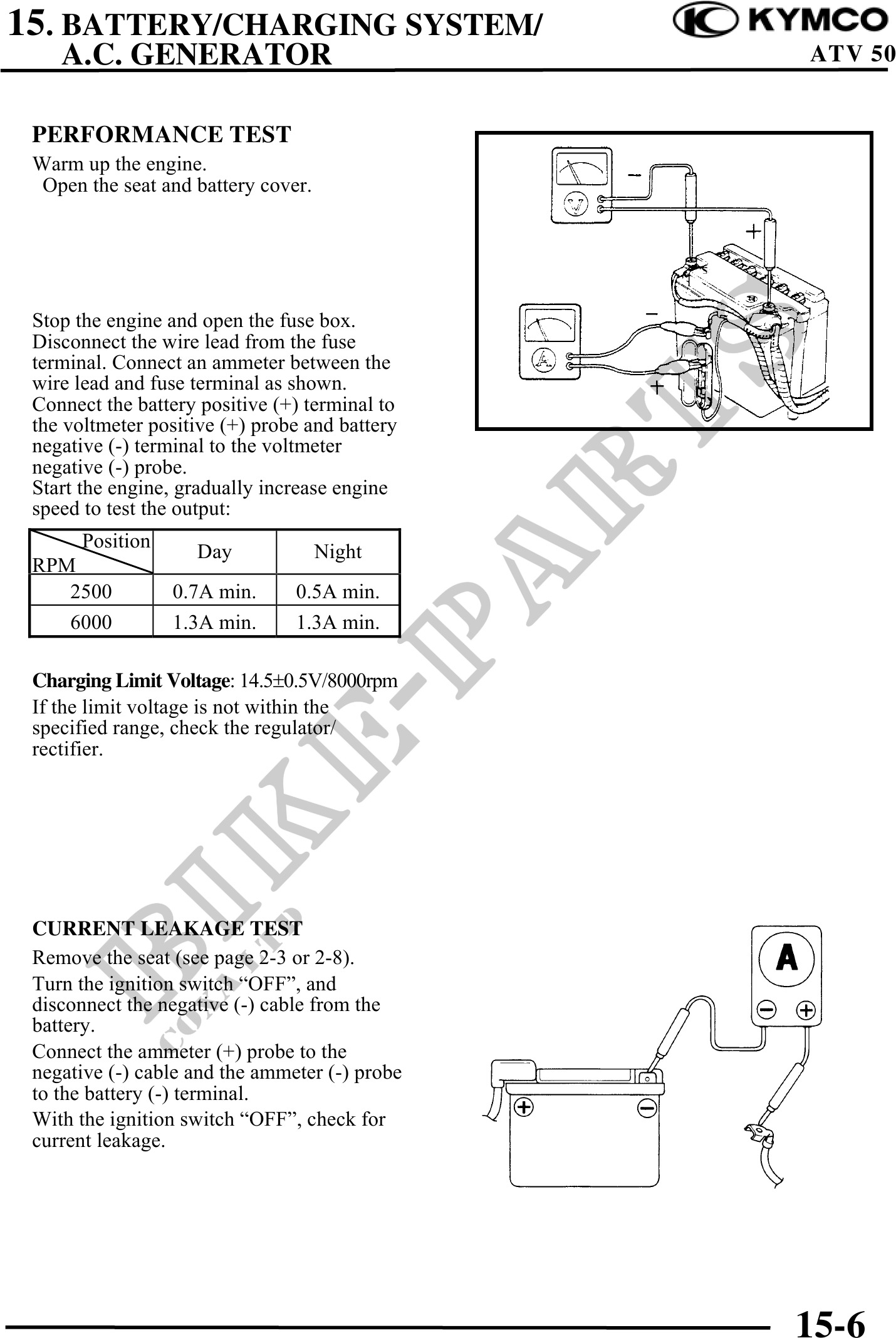
Stop the engine and open the fuse box.
Disconnect the wire lead from the fuse
terminal. Connect an ammeter between the
wire lead and fuse terminal as shown.
Connect the battery positive (+) terminal to
the voltmeter positive (+) probe and battery
negative (-) terminal to the voltmeter
negative (-) probe.
Start the engine, gradually increase engine
speed to test the output:
Position
Day Night
RPM
2500 0.7A min. 0.5A min.
6000 1.3A min. 1.3A min.
Charging Limit Voltage: 14.50.5V/8000rpm
If the limit voltage is not within the
specified range, check the regulator/
rectifier.
CURRENT LEAKAGE TEST
Remove the seat (see page 2-3 or 2-8).
Turn the ignition switch "OFF", and
disconnect the negative (-) cable from the
battery.
Connect the ammeter (+) probe to the
negative (-) cable and the ammeter (-) probe
to the battery (-) terminal.
With the ignition switch "OFF", check for
current leakage.
15-6