14. REAR WHEEL/SWING ARM/
HYDRAULIC BRAKE ATV 50
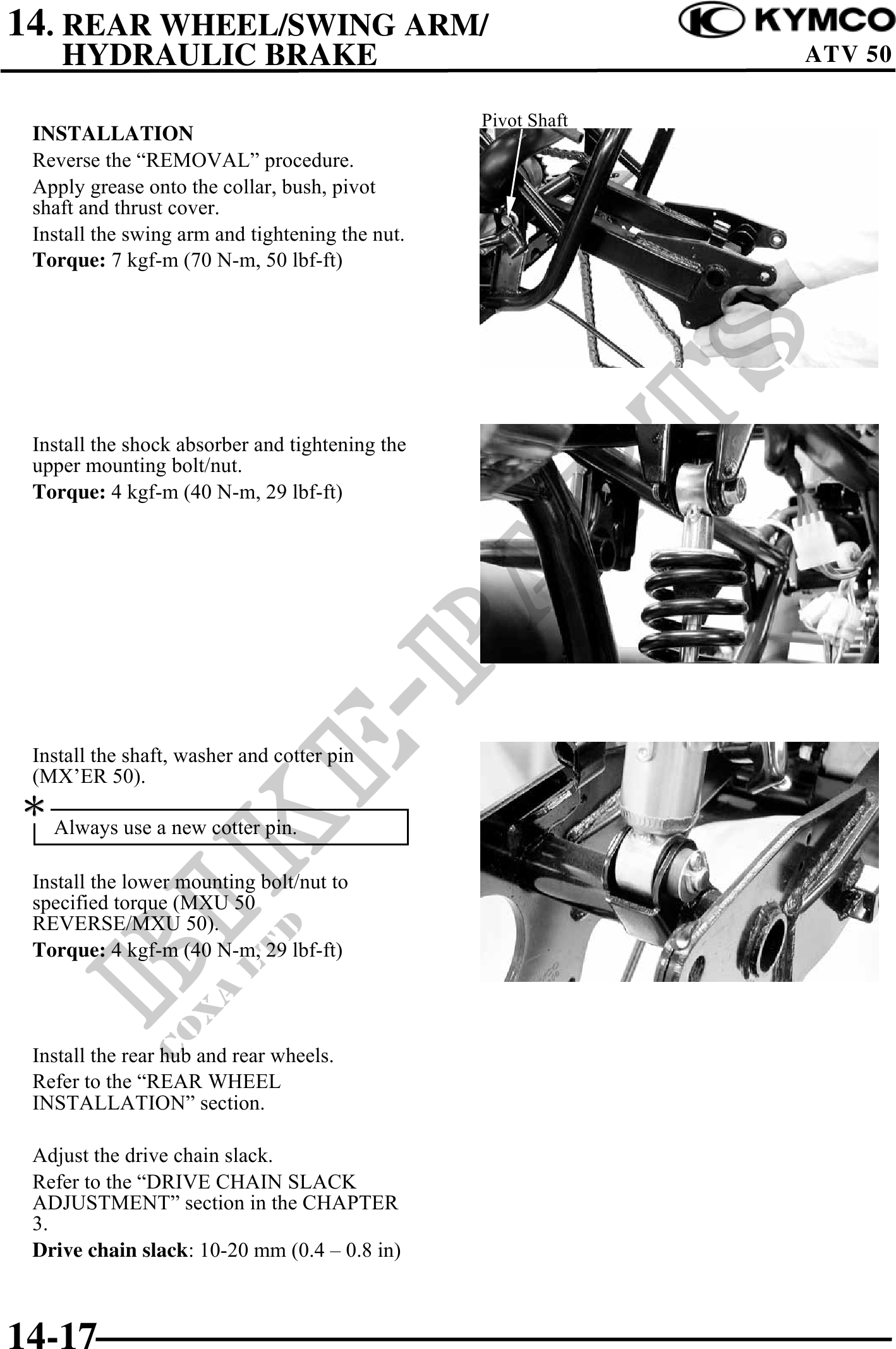
Pivot Shaft
INSTALLATION
Reverse the "REMOVAL" procedure.
Apply grease onto the collar, bush, pivot
shaft and thrust cover.
Install the swing arm and tightening the nut.
Torque: 7 kgf-m (70 N-m, 50 lbf-ft)
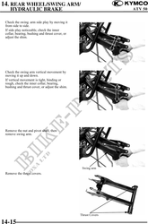
Install the shock absorber and tightening the
upper mounting bolt/nut.
Torque: 4 kgf-m (40 N-m, 29 lbf-ft)
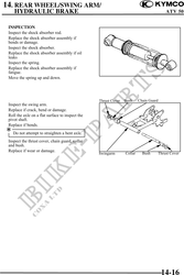
Install the shaft, washer and cotter pin
(MX'ER 50).
.
Always use a new cotter pin.
Install the lower mounting bolt/nut to
specified torque (MXU 50
REVERSE/MXU 50).
Torque: 4 kgf-m (40 N-m, 29 lbf-ft)
Install the rear hub and rear wheels.
Refer to the "REAR WHEEL
INSTALLATION" section.
Adjust the drive chain slack.
Refer to the "DRIVE CHAIN SLACK
ADJUSTMENT" section in the CHAPTER
3.
Drive chain slack: 10-20 mm (0.4 0.8 in)
14-17