grand dink 125 mmc Manuel atelier : Page 59

Microfiches
Image preview

Page 57

Image preview

Page 58

Image preview

Page 60

Image preview

Page 61

1 5 10 15 20 25 30 35 40 45 50 55 60 65 70 75 80 85 90 95 100 105 110 115 120 125 130 135 140 145 150 155 160 165 170 175 180 185 190 195 200 205 210 215 220 225 230 235 240 245 249
          4. LUBRICATION SYSTEM                                                      GRAND DINK 125/150


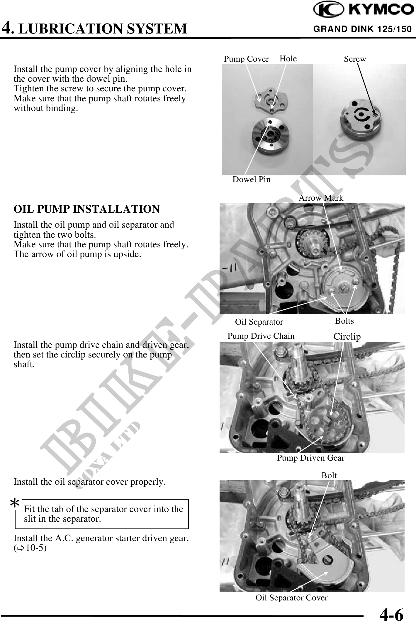
                                                   Pump Cover    Hole                Screw
 Install the pump cover by aligning the hole in
 the cover with the dowel pin.
 Tighten the screw to secure the pump cover.
 Make sure that the pump shaft rotates freely
 without binding.


                                                    Dowel Pin

                                                                        Arrow Mark
 OIL PUMP INSTALLATION
 Install the oil pump and oil separator and
 tighten the two bolts.
 Make sure that the pump shaft rotates freely.
 The arrow of oil pump is upside.


                                                     Oil Separator              Bolts
                                                   Pump Drive Chain             Circlip
 Install the pump drive chain and driven gear,
 then set the circlip securely on the pump
 shaft.


                                                                Pump Driven Gear
                                                                             Bolt
 Install the oil separator cover properly.

 Fit the tab of the separator cover into the
    slit in the separator.
 Install the A.C. generator starter driven gear.
 ( 10-5)


                                                          Oil Separator Cover

                                                                                             4-6