11. CRANKCASE/CRANKSHAFT AGILITY 125
SERVICE INFORMATION.......................11-1 CRANKSHAFT....................................... 11-3
TROUBLESHOOTING .............................11-1 CRANKCASE ASSEMBLY................... 11-4
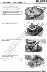
CRANKCASE SEPARATION ..................11-2
SERVICE INFORMATION
GENERAL INSTRUCTIONS
· This section covers crankcase separation to service the crankshaft. The engine must be removed
for this operation.
· The following parts must be removed before separating the crankcase.
-Cylinder head ( Section 7)
-Cylinder/piston ( Section 8)
-Drive and driven pulleys ( Section 9)
-A.C. generator ( Section 14)
-Carburetor/air cleaner ( Section 5)
-Rear wheel/rear shock absorber ( Section 13)
-Starter motor ( Section 16)
-Oil pump ( Section 4)
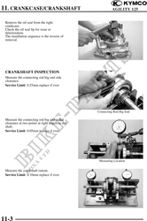
SPECIFICATIONS
Item Standard (mm) Service Limit (mm)
Connecting rod big end side clearance 0.100.35 0.55
Crankshaft Connecting rod big end radial clearance 0-0.008 0.05
Runout 0.10
TORQUE VALUES
Crankcase bolt 0.8~1.2kgf-m
Cam chain tensioner slipper bolt 0.8~1.2kgf-m
TROUBLESHOOTING
Excessive engine noise
· Excessive bearing play
· Excessive crankpin bearing play
11-1